Greetings to everyone! In my previous post, we have discussed about the removal of nitrogen by three different techniques. Today, we are going to look into the sulphur recovery in natural gas system. We have already learnt that sulphur comes in terms of H2S in natural gas. Under acid gas removal we have already learnt the techniques to remove H2S from natural gas. Sulphur is a very important component in manufacture of many chemicals, so the recovered H2S is not thrown out and also H2S is not good for environment. It has many of the deleterious effects which we learnt in our previous posts. So, instead of throwing out the H2S, we try to recover sulphur from H2S.
WHAT WE SHALL LEARN?
In this particular post, we shall be learning about the need of sulphur recovery, the nature of sulphur, classification of sulphur recovery systems, Claus process, acid gas enrichment and oxygen enrichment.
Need of Sulphur Recovery
First, let us see why do we need to recover sulphur. Sulphur is recovered to obtain elemental sulphur used in sulphuric acid manufacture. It is also recovered to use in the fertiliser industry. In the fertiliser industry, the phosphate fertiliser is made from phosphoric acid, which is produced from fluorapatite also known as phosphate rock [ 3Ca3(PO4)2.CaF2] by the addition of concentrated (93%) sulphuric acid. Next, we also need to recover sulphur to use in the rubber industry for the vulcanisation of the rubber. Sulphur is also required to make food preservatives, detergents, surfactants, fungicide, pesticide, herbicide etc. It is also needed to prepare mercaptans which are used to detect leakage of LPG, LNG etc.
Nature of Sulphur
The sulphur is a peculiar component and it exists in various allotropic forms i.e., the number of sulphur atoms may vary with temperature and phase. We can generalise it as Sx where x varies between 1 and 8 depending on the temperature and the phases (solid, liquid, vapor).
The S8 dominates at low temperature and decomposes to S6 and finally to S2 at higher temperature. The clustering of the sulphur atoms has profound effects on physical and thermodynamic properties and on the conversion of H2S to sulphur.
Sulphur Recovery Processes
Depending on the capacity, we have divided them into 3 categories viz. large scale, medium scale and small scale. These has been divided based on the long tones per day. 1 long ton is defined as 1016 kg. This is in contrast with the ton which is 1000 kg.
| Types | Long tones(LT) per day |
|---|---|
| Large Scale | >25 LT/day |
| Medium Scale | 0.2-25 LT/day |
| Small Scale | <0.2 LT/day |

The large scale sulphur recovery processes includes the Claus process, acid gas enrichment, oxygen enrichment, redox process, Shell Claus off-gas treating (SCOT) and sulphur scavenging.
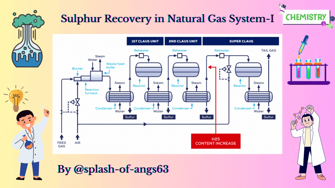
CLAUS PROCESS
This is the most common sulphur recovery process. It involves conversion of the H2S to sulphur via sulphur dioxide formation involving two steps. In the first step, vapor phase combustion of H2S happens and in the second step, catalytic conversion to elemental sulphur occurs.
In the vapor phase oxidation of H2S produces water and sulphur as follows:
3 H2S + 3/2 O2 ⇔ 3 H2O + (3/x) Sx, ΔH = -615000 at 25°C
Although the above reaction defines the overall process but it occurs in two steps as :
Step 1. Thermal combustion reaction
H2S + 3/2 O2 → H2O + SO2 , ΔH = -518900 at 25°C.
Step 2. Catalytic combustion reaction
2H2S + SO2 ⇔ 2H2O + (3/x) Sx , ΔH = -96100 at 25°C.

Straight-through Claus Process
The straight-through Claus process uses a flame reaction furnace ahead of the catalytic stages and all the acid gas is passed through the combustion burner and reaction furnace. It is used when H2S concentration in the acid gas is more than 55%. If the H2S concentration is less than 50% then the temperature falls below a critical point, approximately 1800-2000°F and the flame becomes unstable and cannot be maintained. In this case we need to preheat the acid gas before feeding it to the burner which may overcome the problem of flame instability within limits.
Process Description
The first reaction takes place in a combustion furnace operating near ambient pressure (3 to 8 psig; 0.2 to 0.6 barg). The air flow rate is adjusted to react with one third of the H2S. Other combustibles such as hydrocarbons and mercaptans are also reacted with air. The reaction is exothermic and is used to produce steam in a waste heat boiler. Both the reactions takes place in the furnace-boiler combination. The gases exit the waste-heat boiler in the range of 500 to 650°F which is above the sulphur dew point so that no sulphur condenses in the boiler.

In subsequent catalytic reactors, H2S and SO2 react to give elemental sulphur. Sulphur is recovered after each catalytic combustor using water as the coolant. The vapor leaving each condenser is at the sulphur dew point and hence is reheated to prevent the sulphur deposition on the catalyst.
Split Claus Process
We have already mentioned that the above process is meant for sulphur concentration greater than 50%. In case of sulphuric concentration in the range of 25-40% H2S content Split Claus Process. It has two constraints. Firstly sufficient gas must be bypassed so that the flame temperature is greater than approximately 1700°F. Secondly the maximum bypass is two thirds because one third of the H2S must be reacted to form SO2.
Process Description
The feed is split and one third or more of the feed goes to the furnace which is reacted with air. The combustion of the air is adjusted to oxidise all the H2S to SO2 and the necessary flame temperature can be maintained.
The remainder joins the furnace exit gas and enter the catalytic converter. After that, enough H2S is burned to provide 2:1 ratio of H2S and SO2 in catalytic reactors. We are able to recover after each catalytic reactor some amount of sulphur and ultimately we have tail gas coming coming out from the last condenser. The flame temperature remains above minimum as the heat supplied is absorbed by lower mass of the gas. No H2S remains to react in the furnace.
Sulphur Recovery and Tail Gas Treating
Nitrogen Removal in Natural Gas System-II |ChemFam #21|
Nitrogen Removal in Natural Gas System-I |ChemFam #20|
Acid Gas Removal in Natural Gas System-II |ChemFam #19|
Acid Gas Removal in Natural Gas System-I |ChemFam #18|
Estimation of Water Content in Natural Gas |ChemFam #17|
Membrane Separation in Natural Gas System |ChemFam #16|
Design of distillation column |ChemFam #15|
Separation Technique: Distillation |ChemFam #14|
Transmission Electron Microscope: Principle and Working |ChemFam #13|
Scanning Electron Microscope: Principle and Working |ChemFam #12|
Drugs: Classification and drug-target interaction |ChemFam #11|
What are orbitals and quantum numbers? |ChemFam #10|
Quantum mechanical model of an atom |ChemFam #09|
A case study about the growth mechanism of CNT |ChemFam #08|
Carbon Nanotubes (Buckytubes): Types and Synthesis |ChemFam #07|
Nanomaterials: Classification and Approach for Synthesis |ChemFam #06|
Azadirachtin: Isolation, Extraction and Mechanism of Action |ChemFam #05|
Woodward-Fieser Rules for Calculating λmax |ChemFam #04|
Chemistry in ancient India |ChemFam #03|
How do soaps clean the dirt? |ChemFam #02|
What is anti egg white injury factor? |ChemFam #01|
PS The thumbnail image is being created by me using canva.com taking template image from oeuk
