Greetings to everyone! In my previous post, we were discussing about the removal of acid gas in natural gas system. We have discussed the absorptive acid gas removal and understood the typical arrangement of a physical absorption unit. To further study the acid gas removal, I have divided the topic into two parts. So, this is going to be the second part of it and we shall be discussing more about acid gas removal.
WHAT WE SHALL LEARN?
We shall be learning about the acid gas removal in natural gas by various situations and methods. These could be achieved by membrane separation, adsorption phenomena, use of sulphide scavenger and by using low temperature for the removal of acid gases.
MEMBRANE SEPARATION FOR ACID GAS REMOVAL
First let us discuss the membrane separation for acid gas removal. The membrane we shall be using are some polymeric membranes.
| Acid gas | Preferred polymer material | Polymer used | Selective over CH4 (%) |
|---|---|---|---|
| CO2 | Glassy | Cellulose acetate, Polyimide, Perfluoro polymer | 10-20 |
| H2S | Rubbery | Amide block copolymer | 20-30 |
Cellulose acetate
The cellulose acetate are most commonly used for acid gas removal. They consist of a thin layer having width of about 0.1 to 0.5 µm of cellulose acetate on top of a thicker layer of a porous support. It is an asymmetric membrane which we have already learnt in our previous discussions. These membranes possesses highest CO2 selectivity over CH4 but they are non reactive to most organic solvents.
PARAMETERS AFFECTING MEMBRANE PERFORMANCE
There are few parameters which influences the performance of this membranes. The three major parameters we shall be discussing here are Flow rate, Operating temperature and Operating pressure.
✓ Flow rate
The membrane performance degrade at higher flow rates. So, for better membrane performance, we need to operate it at reduced feed rates. Simultaneously performance drops above the designed flow rate. We also need to have additional modules of the membrane if we have to handle larger flow rates.
✓ Operating temperature
An increase in operating temperature increases membrane permeability and on the contrary decreases membrane selectivity. Exceeding the maximum operating temperature degrades membrane material and shorten the useful life span of the unit.
✓ Operating pressure
With the increase in operating pressure or feed pressure, both the permeability and the selectivity decreases. An increased in pressure difference across the membrane increases the net flow rate through the membrane.
FEED GAS PRE-TREATMENT
In case of membrane, we meed to pre-treat the gas because the membrane force may get chocked by some particulate matters. So, it is required due to the reduced susceptibility of membranes to degradation by impurity. There can be several types of impurities. Suppose, we have liquid impurity in the system, then these liquid impurities can cause the membrane swelling and result in decreased flux rates and possible membrane damage. The heavier hydrocarbons can coat the surface of the membrane which decreases flux rates and results in a loss of performance. The particulates can block the small flow passages in the membrane. Therefore, we need to pre-treat the feed before allowing it to go to the membrane module.
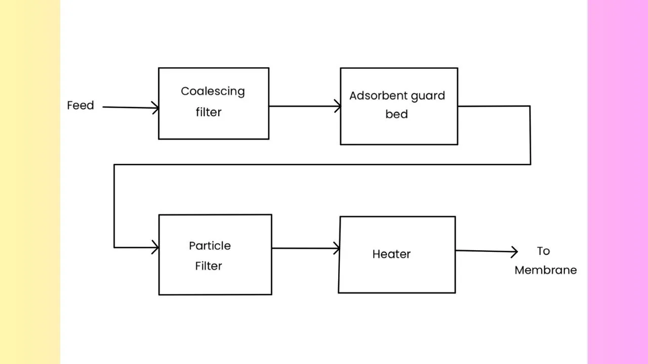
Here we have shown a typical membrane system configuration for the pre-treatment of the feed. The feed comes to the membrane through a series of filtration units. First the feed moves into a mechanical filter and then it passes into a adsorbent filter and then into a particulate filter. After filtration, the feed is heated and then finally it goes into the actual membrane module.
ADVANTAGES OF THE MEMBRANE SEPARATION
There are numerous advantages of choosing membrane separation. Firstly, it is cost effective when compared to other solvent systems. It is easy to operate and can be installed with ease. Their construction are simple as they do not contain any kind of moving part mostly for single-stage units. They have high turndown ratio i.e., the ratio between the highest to lowest feed rate that they can handle. They do not need any kind of chemicals and occupies less space.
ADSORPTIVE ACID GAS REMOVAL
It is less popular than the absorptive acid gas removal which we have discussed already in the previous post. Here, at ambient temperature; substantial quantities of both gases i.e., CO2 and H2S are adsorbed even at low partial pressures. The adsorbents used may be molecular sieves which can be zeolites or activated carbon or these can be metal oxides like metal organic framework (MOF).
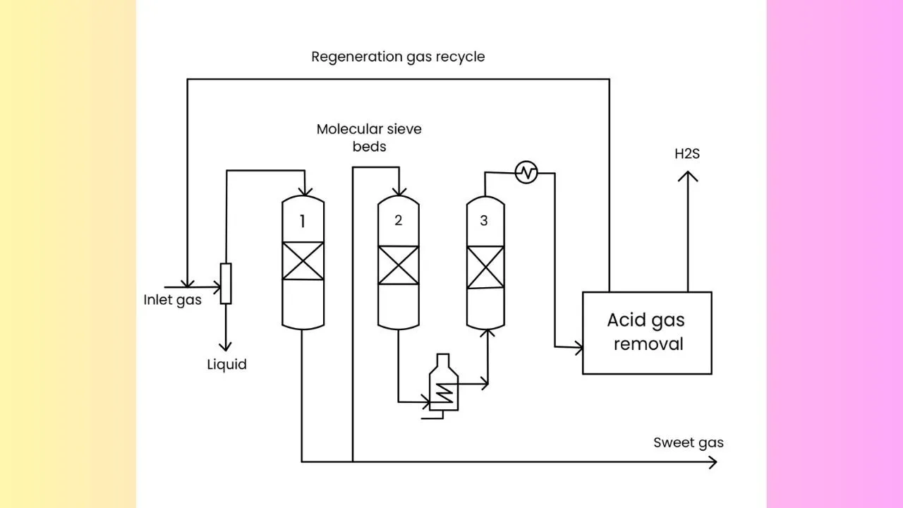
A typical adsorptive unit for H2S removal
Here, we have the feed gas which passes through various beds. It is interesting no note that not all beds are performing adsorption at the same time. Suppose, bed 1 is undergoing adsorption and bed 3 is undergoing regeneration with hot gas and bed 2 cools down after regeneration. Typically we find 3 adsorption beds to carry out H2S removal but it can range from 2 to 4 depending on different times for cooling down.
ACID GAS REMOVAL BY SULPHIDE SCAVENGER
These scavengers are used when the quantity of sulphur to be recovered is small in the range of 400 lb/ day or less. It uses small scale batch processes for H2S removal and the scavengers are non regenerable. They chemically react with sulphur compounds to convert them to more inert forms.
The scavengers should react completely and rapidly with the sulphides and should have the ability to react in an wide range of chemical and physical environments like pH, temperature, pressure etc. They should be non-corrosive and easy to to avail. These should not pose a threat to health of personnel or pollute the environment.
Removal of H2S by iron oxide
Iron oxide is the very popular among many other sulphide scavengers. The process occurs as a redox reaction by using iron as an oxidising agent in a solution. In the first step the H2S is removed from the gas by adsorption into a caustic solution. Then oxidation of the HS- ion to elemental sulphur occurs via the oxidising agent. In the next step, sulphur is removed and separated from the solution. Finally the oxidising agent is regenerated by use of air. The overall steps can be summarised in a redox reaction as,
Fe3O4 + 6H2S → 3FeS2 + 4H2O + 2H2
Journal of petroleum science and engineering
Acid gas removal-an overview by ScienceDirect
Acid Gas Removal in Natural Gas System-I |ChemFam #18|
Estimation of Water Content in Natural Gas |ChemFam #17|
Membrane Separation in Natural Gas System |ChemFam #16|
Design of distillation column |ChemFam #15|
Separation Technique: Distillation |ChemFam #14|
Transmission Electron Microscope: Principle and Working |ChemFam #13|
Scanning Electron Microscope: Principle and Working |ChemFam #12|
Drugs: Classification and drug-target interaction |ChemFam #11|
What are orbitals and quantum numbers? |ChemFam #10|
Quantum mechanical model of an atom |ChemFam #09|
A case study about the growth mechanism of CNT |ChemFam #08|
Carbon Nanotubes (Buckytubes): Types and Synthesis |ChemFam #07|
Nanomaterials: Classification and Approach for Synthesis |ChemFam #06|
Azadirachtin: Isolation, Extraction and Mechanism of Action |ChemFam #05|
Woodward-Fieser Rules for Calculating λmax |ChemFam #04|
Chemistry in ancient India |ChemFam #03|
How do soaps clean the dirt? |ChemFam #02|
What is anti egg white injury factor? |ChemFam #01|
PS The thumbnail image is being created by me using canva.com taking template image from ScienceDirect
