Assembly and Commissioning
Part 1 can be found here: @lichtkunstfoto/diy-star-tracker-part-1
The original OG Star Tracker was designed by Ondra Gejdos. Thank you for making the idea, the files for the 3D printer, the parts list and the instructions freely available.
https://www.ogstartech.com/home/

Step One - 3D Printing
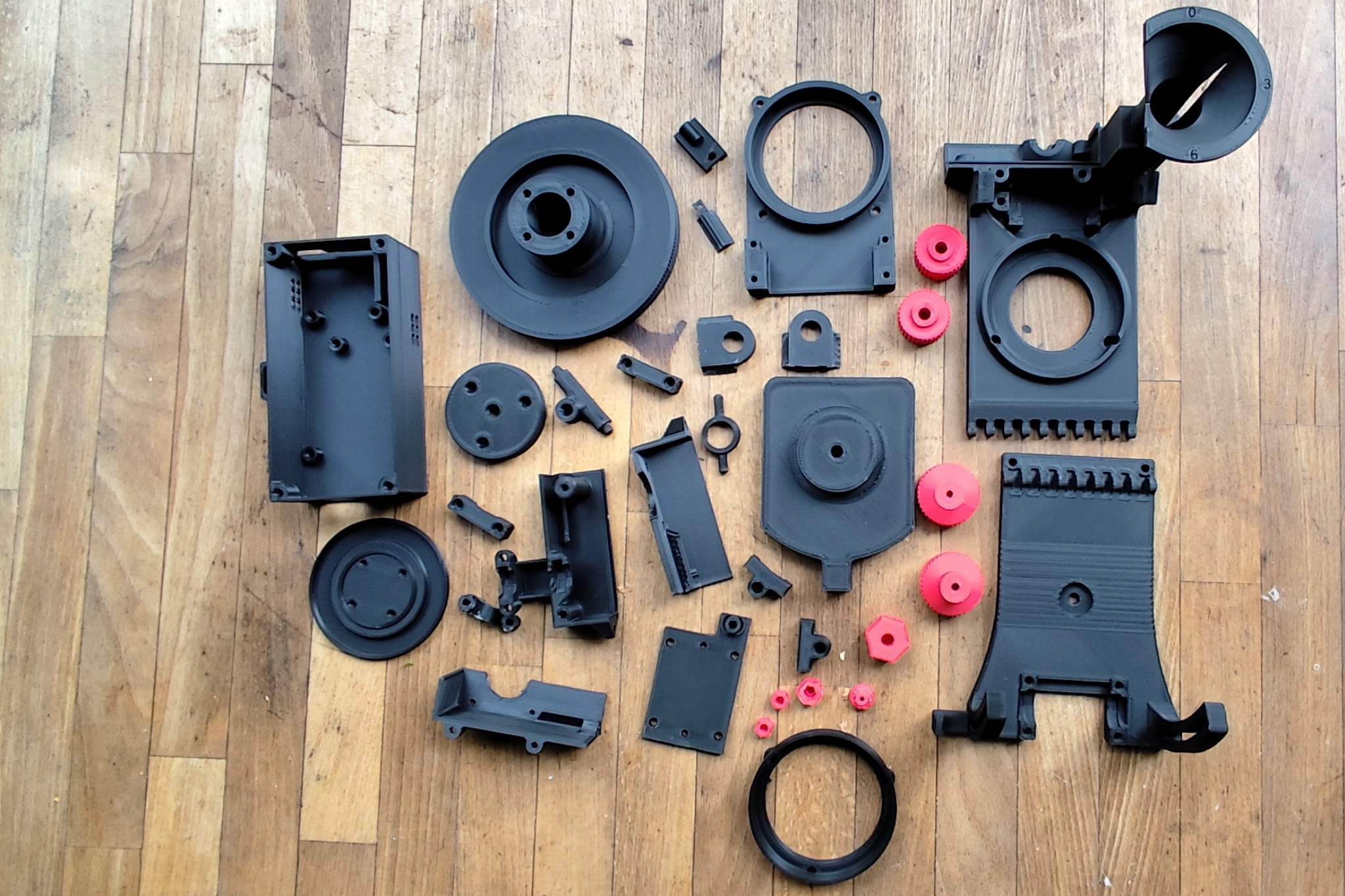
First I printed out all the parts I needed with the Creality Ender 3. You can see all 33 parts in the cover picture. So not all of them. The cover for the box in which the electronics are housed is missing. I used over 900 g of filament in total. I used Extrudr NX-2 in black and Hellfire Red. This is a fairly easy to process, matt PLA. The total printing time for all the parts was around 90 hours. I could have shortened the time if I had screwed a print nozzle with a larger opening into the hotend, printed at a higher speed and increased the layer height. After a short test with a layer height of 0.28 mm and a print speed of 150 mm/s, I discarded this idea. The layer adhesion of the NX-2 is not particularly good anyway, so I then printed all the parts with a 0.2 mm layer and 60 mm/s. This ensured that all the parts were stable and that nothing would wobble or even break later on.
I built a total of four pieces. I assembled the second one yesterday. Number three is currently being printed. So I'll be busy for a while yet.
Zuerst habe ich alle benötigten Teile mit dem Creality Ender 3 ausgedruckt. Im Titelbild seht ihr alle 33 Teile. Also nicht ganz. Es fehlt der Deckel für die Box, in der die Elektronik untergebracht wird. Insgesamt habe ich über 900 g Filament verarbeitet. Ich habe Extrudr NX-2 in Schwarz und Hellfire Red verwendet. Das ist ein recht einfach zu verarbeitendes, mattes PLA. Die gesamte Druckzeit für alle Teile lag bei ungefähr 90 Stunden. Ich hätte die Zeit verkürzen können, wenn ich eine Druckdüse mit größerer Öffnung in das Hotend geschraubt hätte, mit höherer Geschwindigkeit gedruckt hätte und die Layerhöhe vergrößert hätte. Nach einem kurzen Test mit 0,28 mm Layerhöhe und 150 mm/s Druckgeschwindigkeit habe ich das verworfen. Die Layerhaftung des NX-2 ist ohnehin nicht besonders gut, also habe ich dann alle Teile mit 0,2 mm Layer und 60 mm/s gedruckt. Somit war sichergestellt, dass alle Teile stabil sind und später nichts wackelt oder gar zerbricht.
Insgesamt baue ich vier Exemplare. Das zweite habe ich gestern zusammen gebaut. Nummer drei wird gerade gedruckt. Ich bin also noch eine Weile beschäftigt.
Step Two - Threaded Inserts
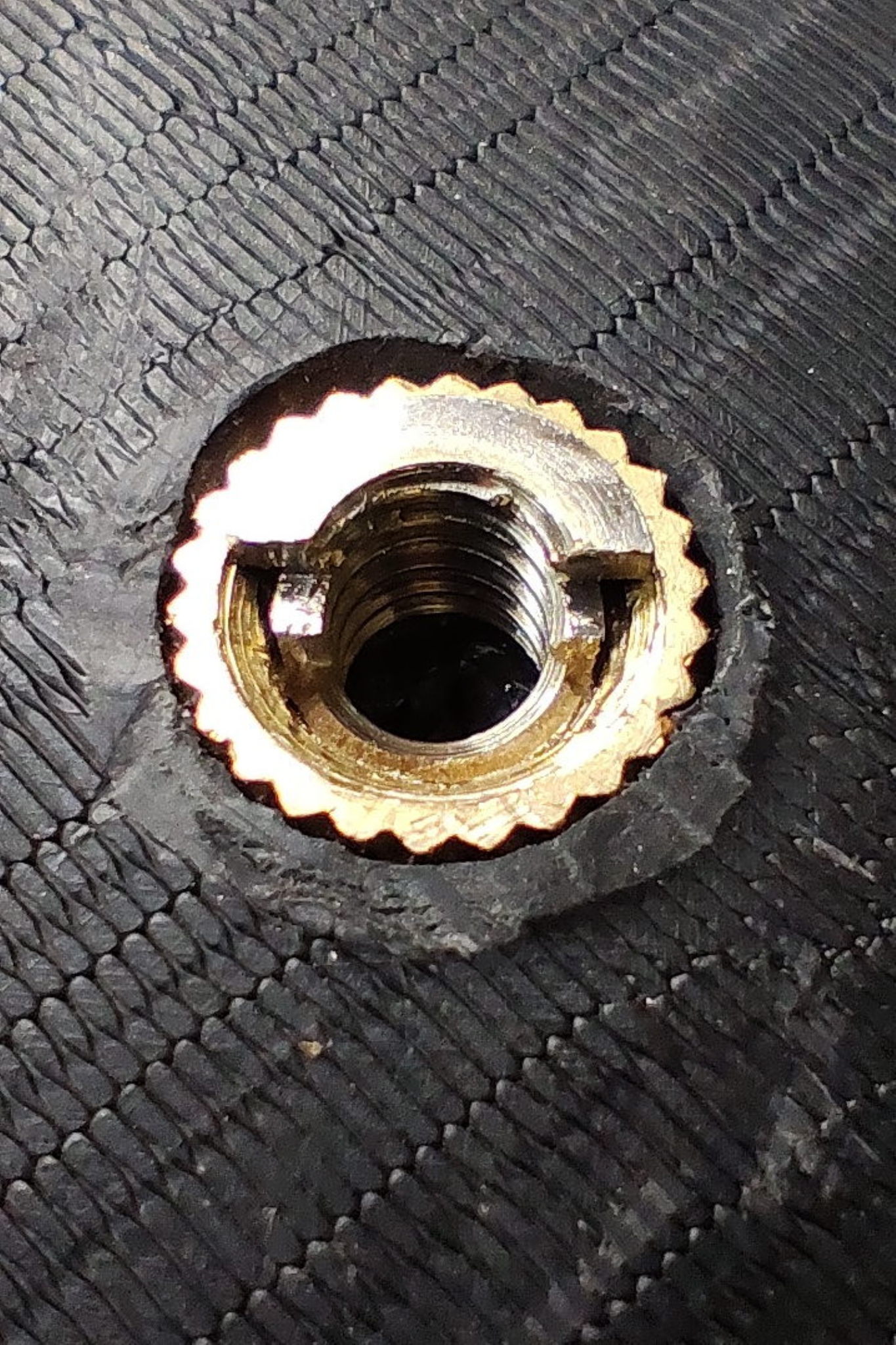
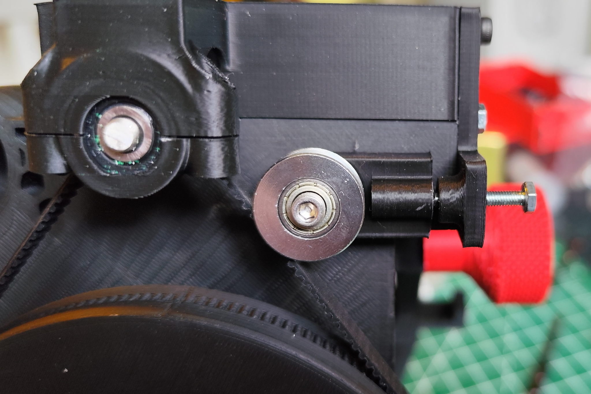
In order to be able to screw the parts together, I melted threaded inserts in the appropriate places. You could also design threads directly into the holes in the CAD programme, but this is not as stable as the threaded inserts. The inserts are heated with a soldering iron and a suitable adapter, the plastic melts and the insert is pressed into the component. After cooling, the thread is firmly anchored in the component. Mechanically, this is highly resilient. As you can see in the next picture, the thread, or in this case a reducing sleeve, usually breaks rather than the thread insert breaking out of the plastic.
Um die Teile miteinander verschrauben zu können, habe ich an den entsprechenden Stellen Gewindeeinsätze eingeschmolzen. Man könnte auch Gewinde im CAD Programm direkt in die Löcher konstruieren, allerdings ist das nicht so stabil, wie die Gewindeeinsätze. Die Einsätze werden mit dem Lötkolben und einem entsprechenden Adapter erhitzt, der Kunststoff schmilzt dabei und der Einsatz wird in das Bauteil gedrückt. Nach dem Abkühlen ist das Gewinde fest im Bauteil verankert. Mechanisch ist das hochbelastbar. Wie man im nächsten Bild sehen kann, zerbricht meist das Gewinde, oder in diesem Fall eine Reduzierhülse, als dass der Gewindeeinsatz aus dem Kunststoff herausbrechen würde.
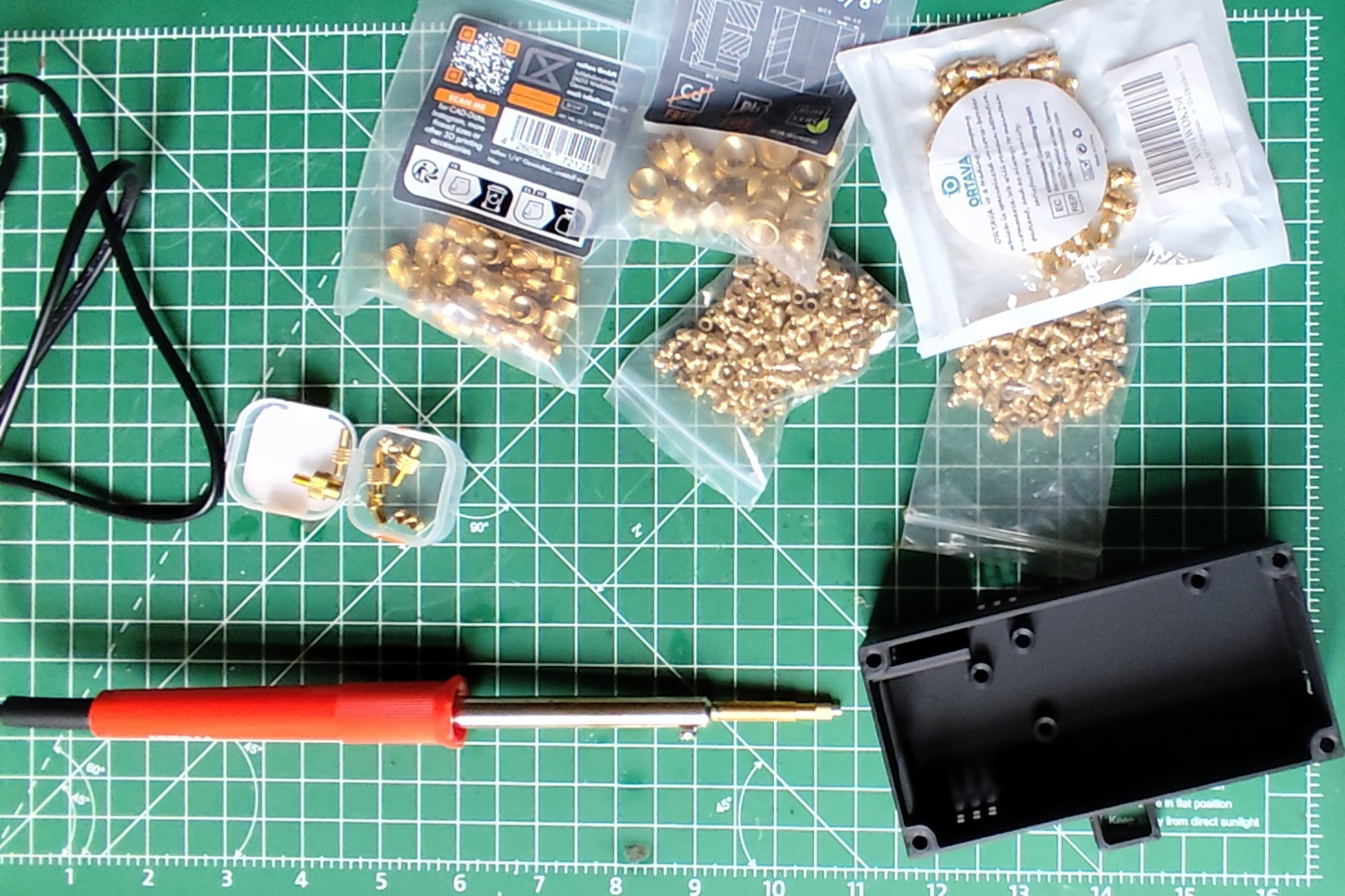
If I haven't miscounted, I have melted 65 threaded inserts of different sizes into the components. I used a normal, unregulated soldering iron with 30 watts. You have to be careful in some places not to hit the component with the soldering iron. The material would then melt immediately at this point and the component would be ruined.
Wenn ich mich nicht verzählt habe, habe ich 65 Gewindeeinsätze verschiedener Größe in die Bauteile geschmolzen. Benutzt habe ich einen normalen, ungeregelten Lötkolben mit 30 Watt. Man muss an einigen Stellen aufpassen, dass man mit dem Lötkolben nicht gegen das Bauteil kommt. Das Material würde an dieser Stelle dann sofort schmelzen und das Bauteil wäre versaut.
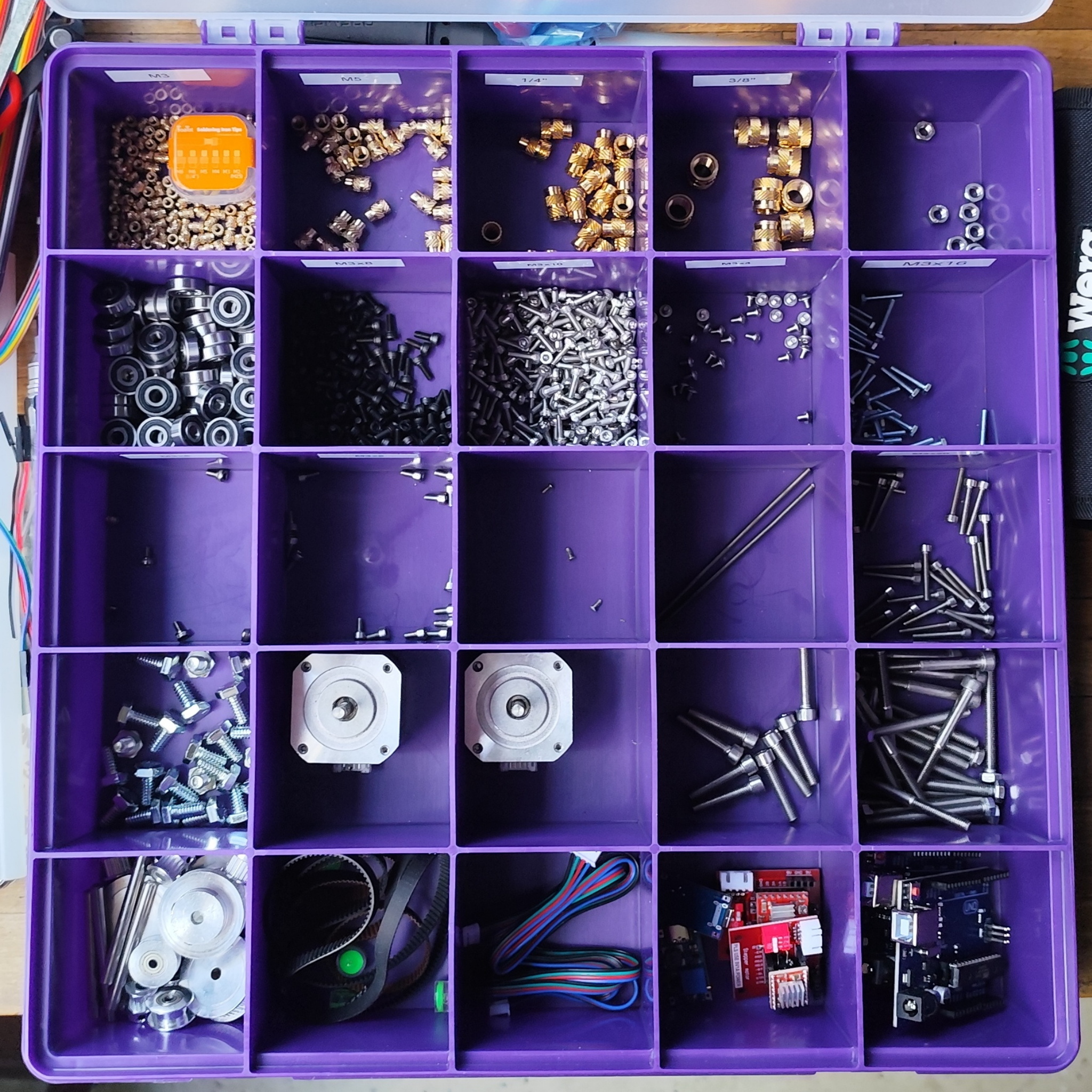
Step Three - Screw it all together
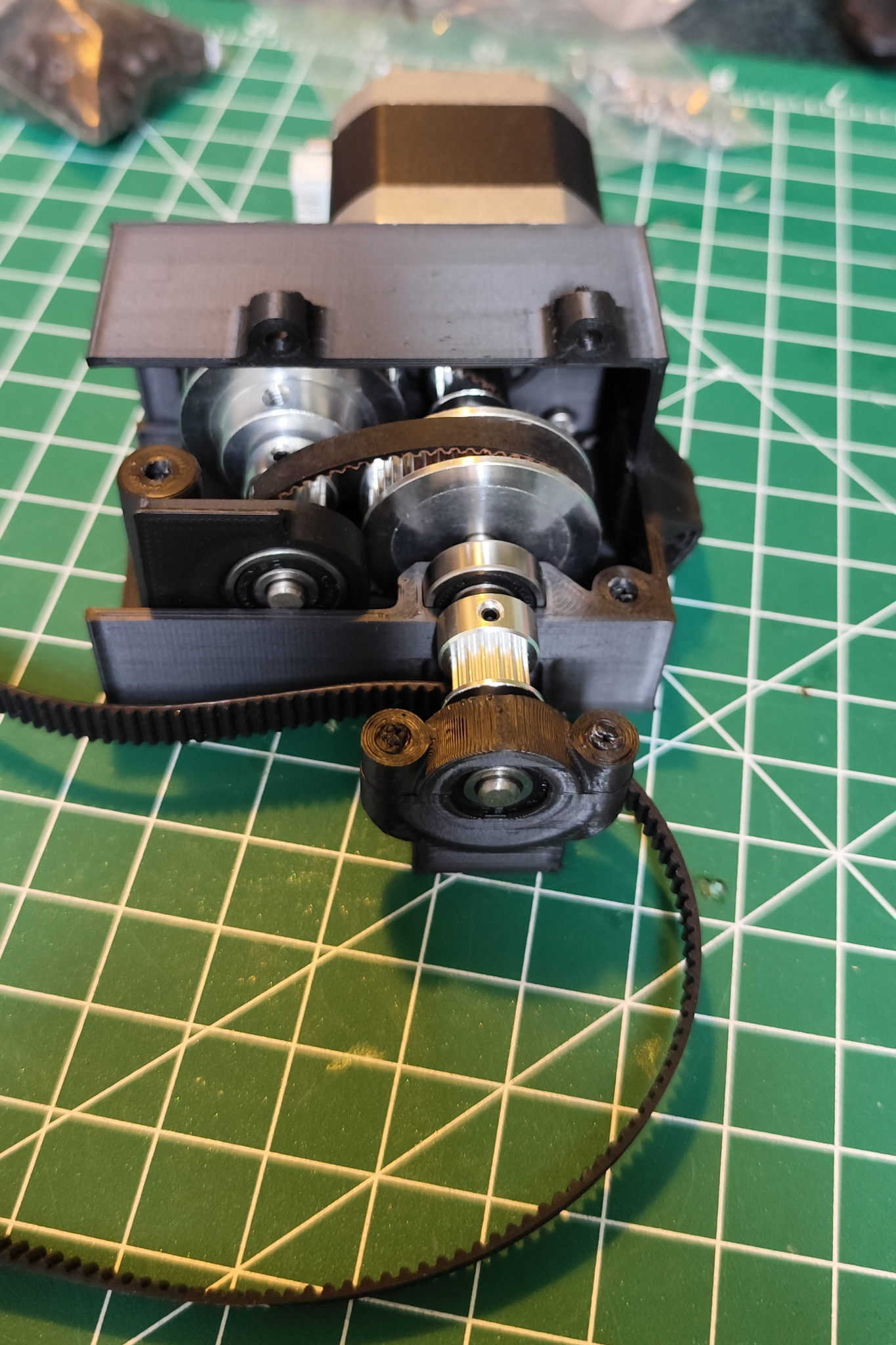
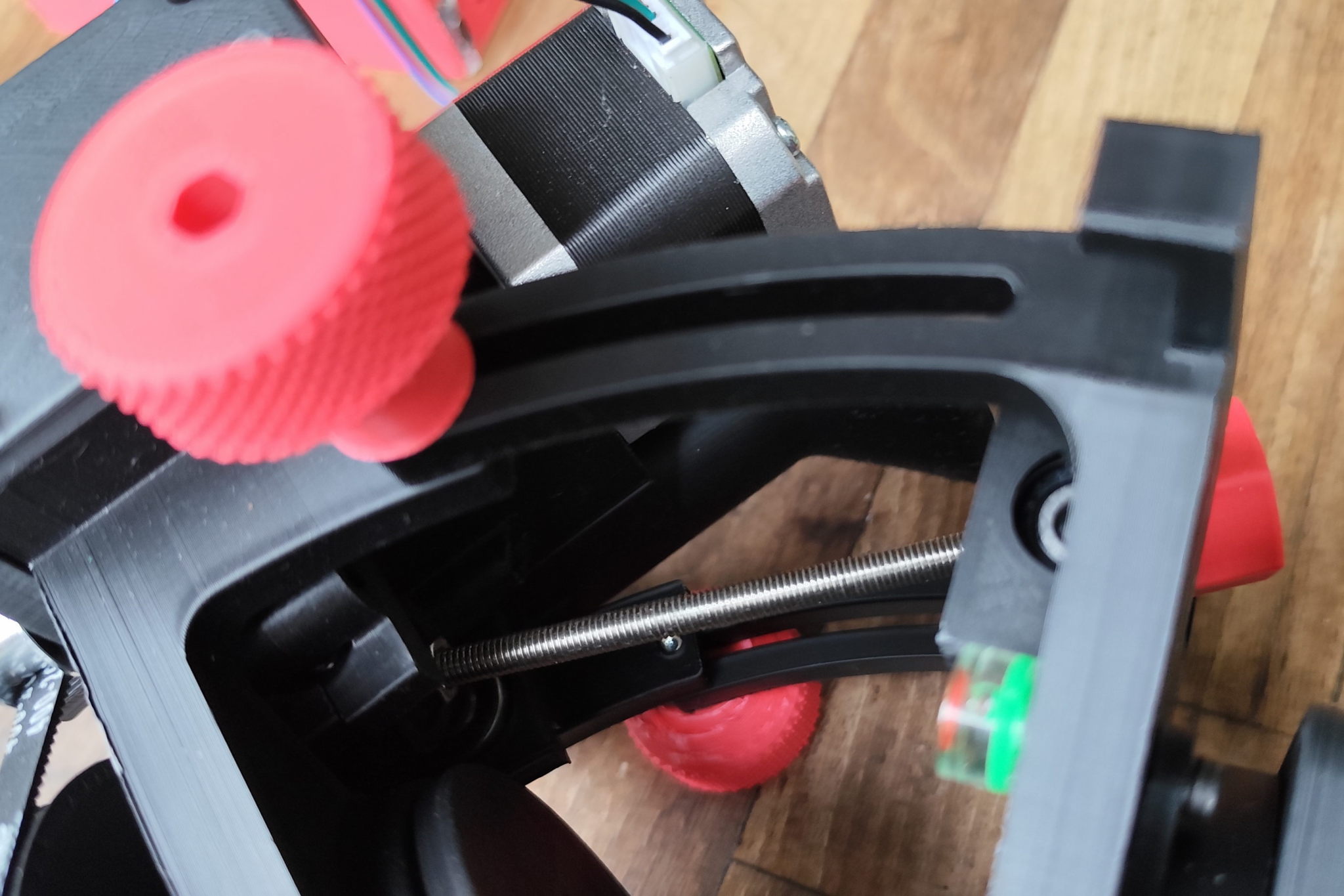

The Star Tracker contains 69 screws, 14 ball bearings, 5 gear wheels. 3 toothed belts and the stepper motor. At first, I had everything in a large cardboard box. That was a stupid idea. I spent most of my time looking for the right screws. Some time ago, my neighbour gave me a large box with lots of compartments. Well, the colour is ugly, but it's better than rummaging around in the big box for hours.
Im Star Tracker sind 69 Schrauben, 14 Kugellager, 5 Zahnräder. 3 Zahnriemen und der Steppermotor verbaut. Zuerst hatte ich alles in einem großen Karton. Das war eine blöde Idee. Die meiste Zeit verbrachte ich mir der Suche nach den passenden Schrauben. Meine Nachbarin hat mir vor einiger Zeit eine große Box mit vielen Fächern geschenkt. Na ja, die Farbe ist hässlich, aber besser als noch stundenlang in dem großen Karton kramen.
Ondra has documented the assembly very well in two videos. Without the videos, it would have taken me much longer to see the finished Star Tracker, at least for the first one.
Die Montage hat Ondra in zwei Videos sehr gut dokumentiert. Ohne die Videos hätte ich, zumindest beim ersten Exemplar, wesentlich länger gebraucht, bis der fertige Star Tracker vor mir gestanden hätte.
Step Four - Electronic

A driver and suitable circuit board are required to drive the stepper motor. A voltage regulator with USB C port is used for the power supply. The movement of the Star Tracker is controlled with an Arduino. I have installed an Arduino Uno, but it will also work with any other model.
Zum Antreiben des Steppermotors wird ein Treiber samt passender Platine benötigt. Zur Stromversorgung wird ein Spannungsregler mit USB C Port verwendet. Gesteuert wird die Bewegung des Star Trackers mit einem Arduino. Ich hab einen Arduino Uno verbaut, das funktioniert allerdings auch mit jedem anderen Modell.
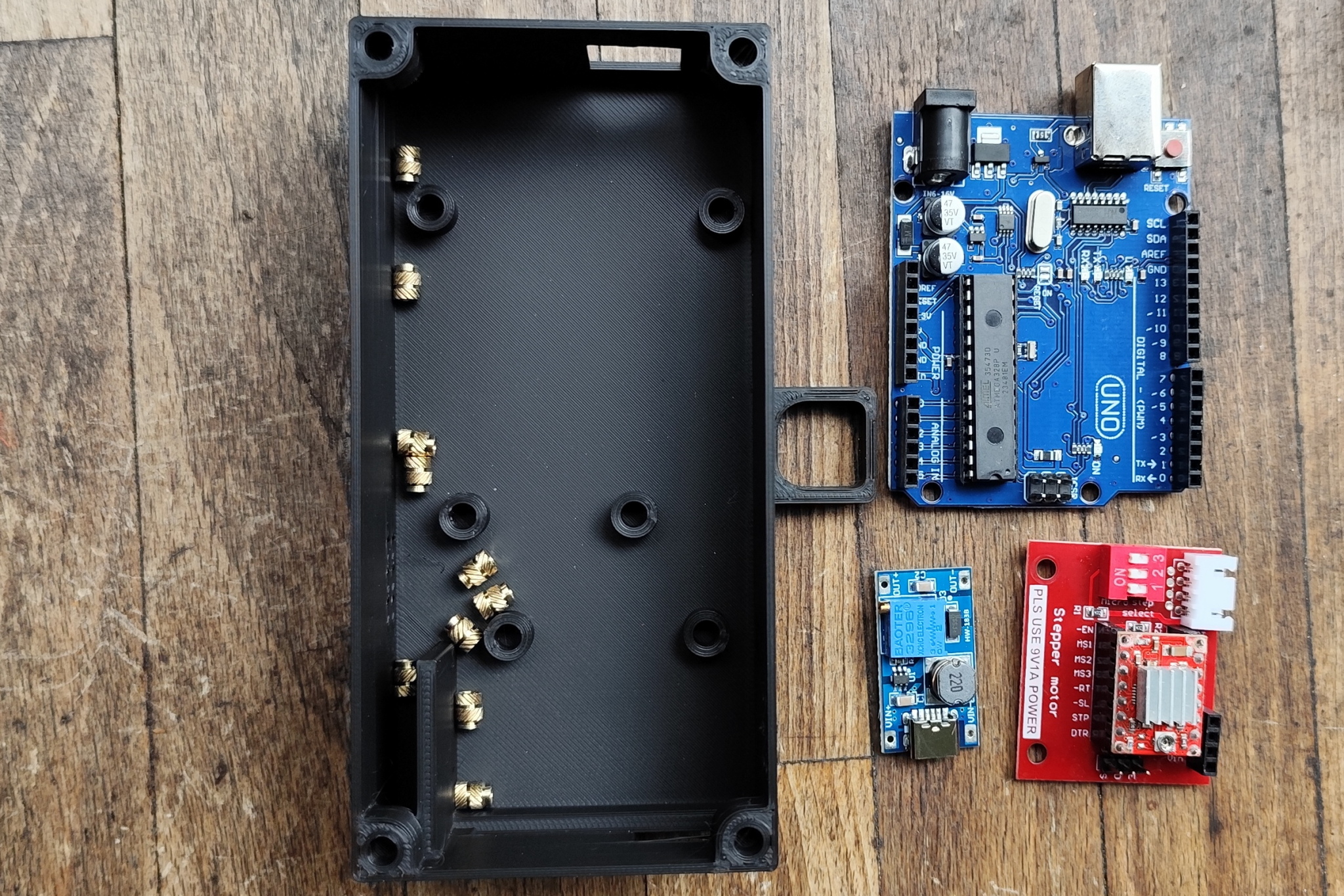
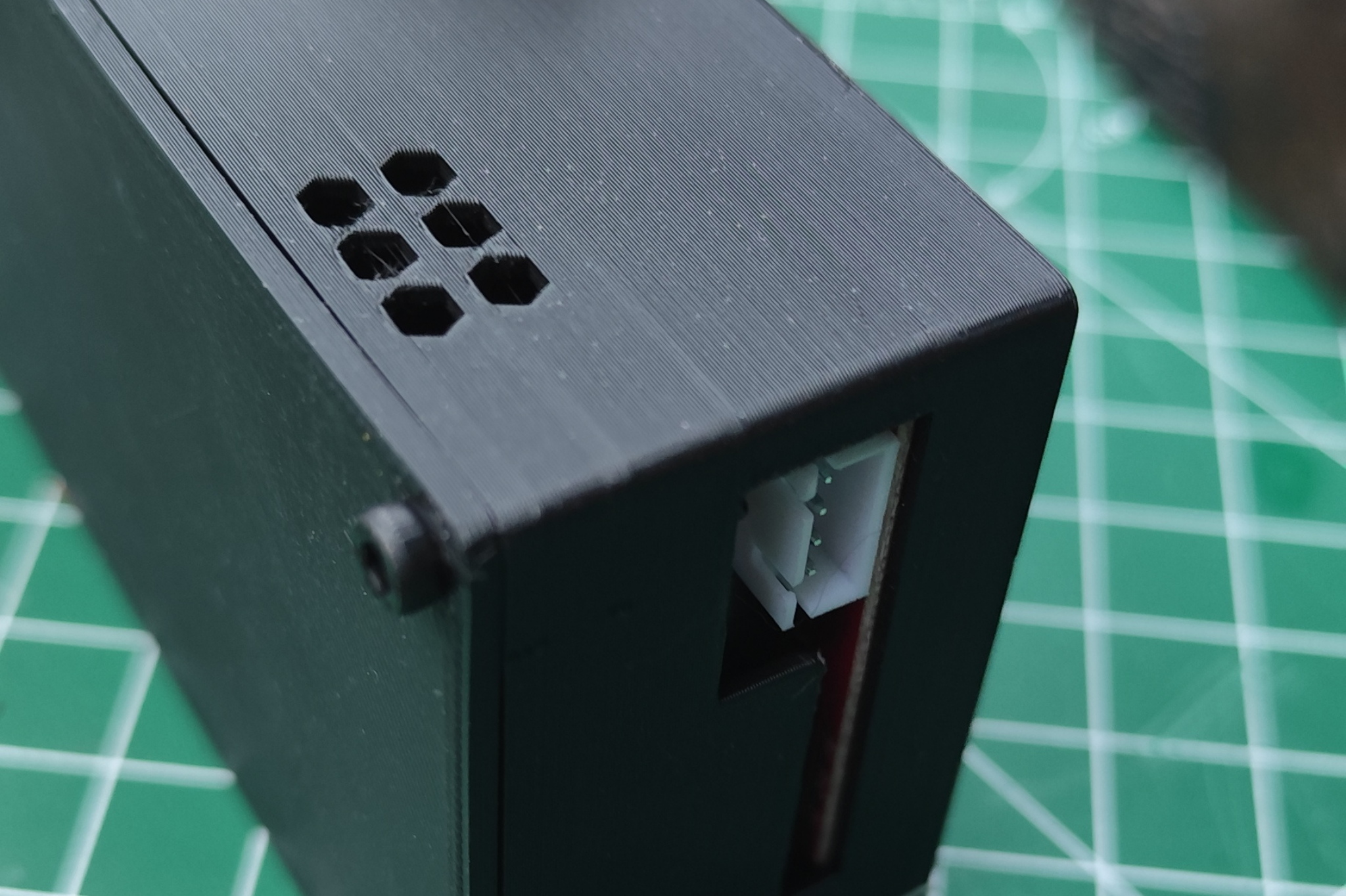
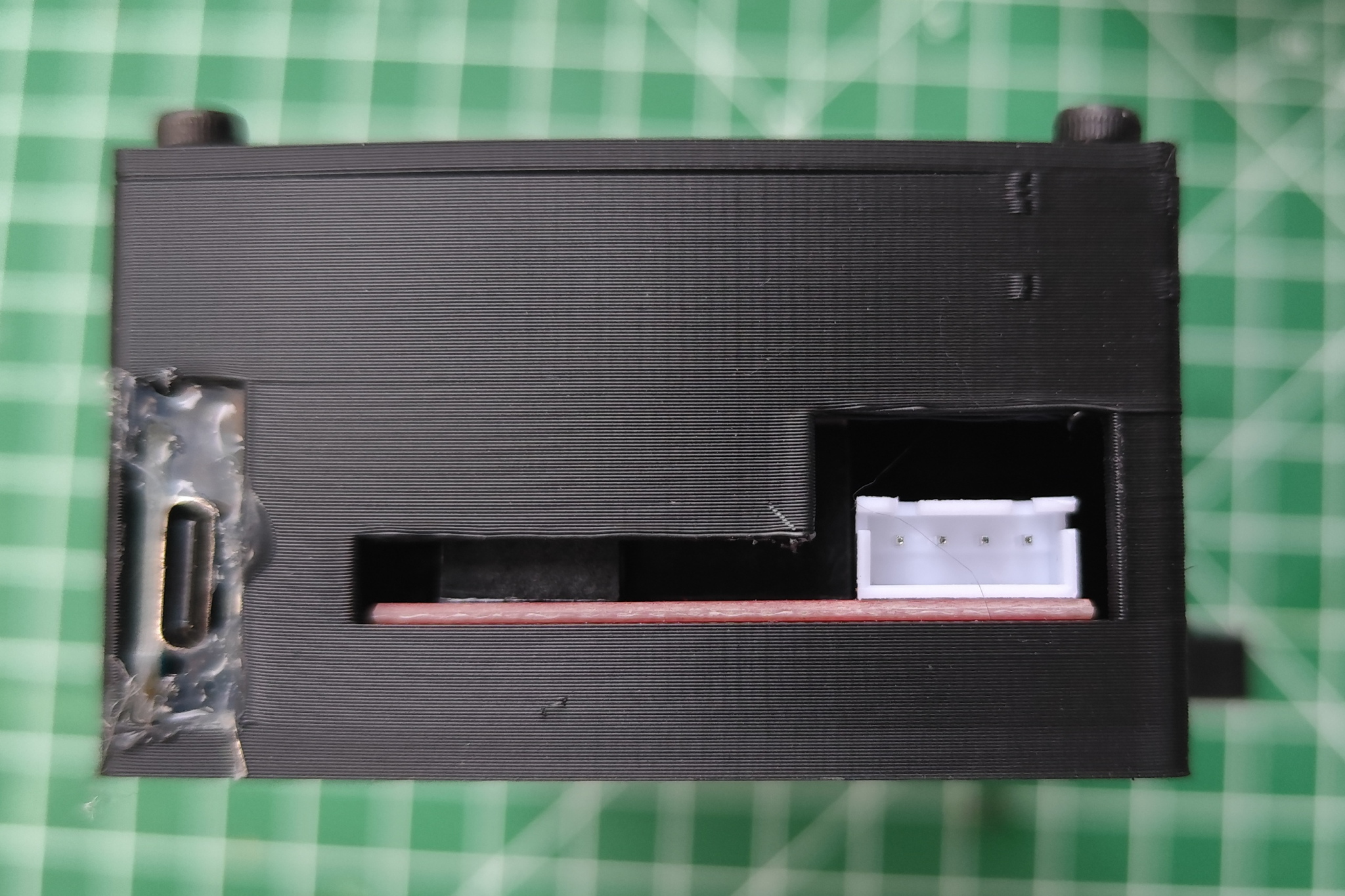
The original housing does not offer the option of fastening the Arduino with screws. For this reason, I designed a new housing using FreeCAD. In addition to the parts for the threaded inserts, I designed some holes for better cooling at the top and bottom of the housing, as well as an opening for the Arduino's USB port. If you want to use the Star Tracker in the southern hemisphere, you have to change the Arduino programme. So 
Das originale Gehäuse bietet keine Möglichkeit, den Arduino mit Schrauben zu befestigen. Aus diesem Grund habe ich ein neues Gehäuse mit FreeCAD konstruiert. Neben den Teilen für die Gewindeeinsätze habe ich einige Löcher zur besseren Kühlung oben und unten im Gehäuse sowie eine Öffnung für den USB-Port des Arduino konstruiert. Wenn man den Star Tracker auf der Südhalbkugel verwenden will, muss das Programm des Arduino verändert werden. Also braucht
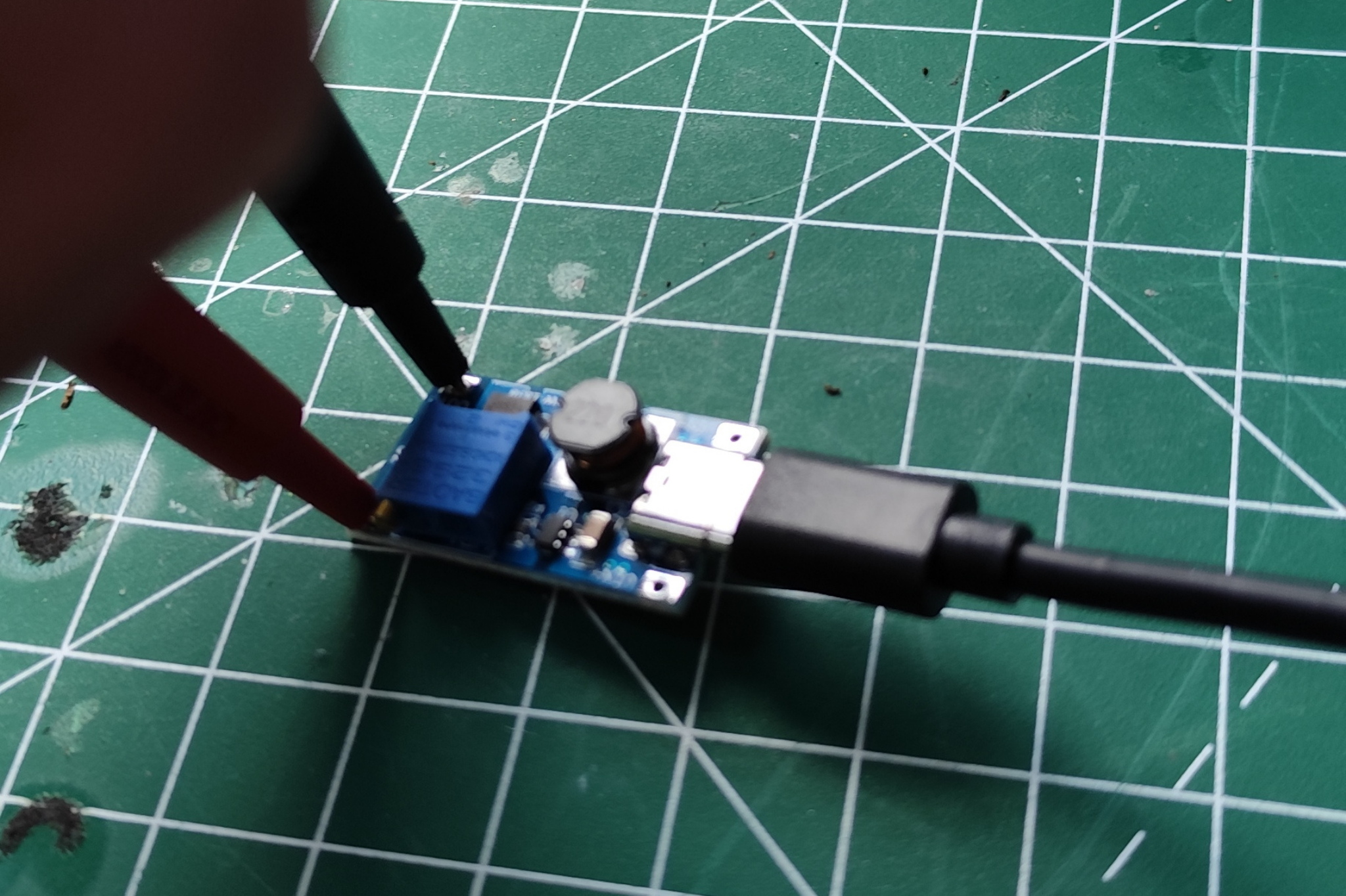
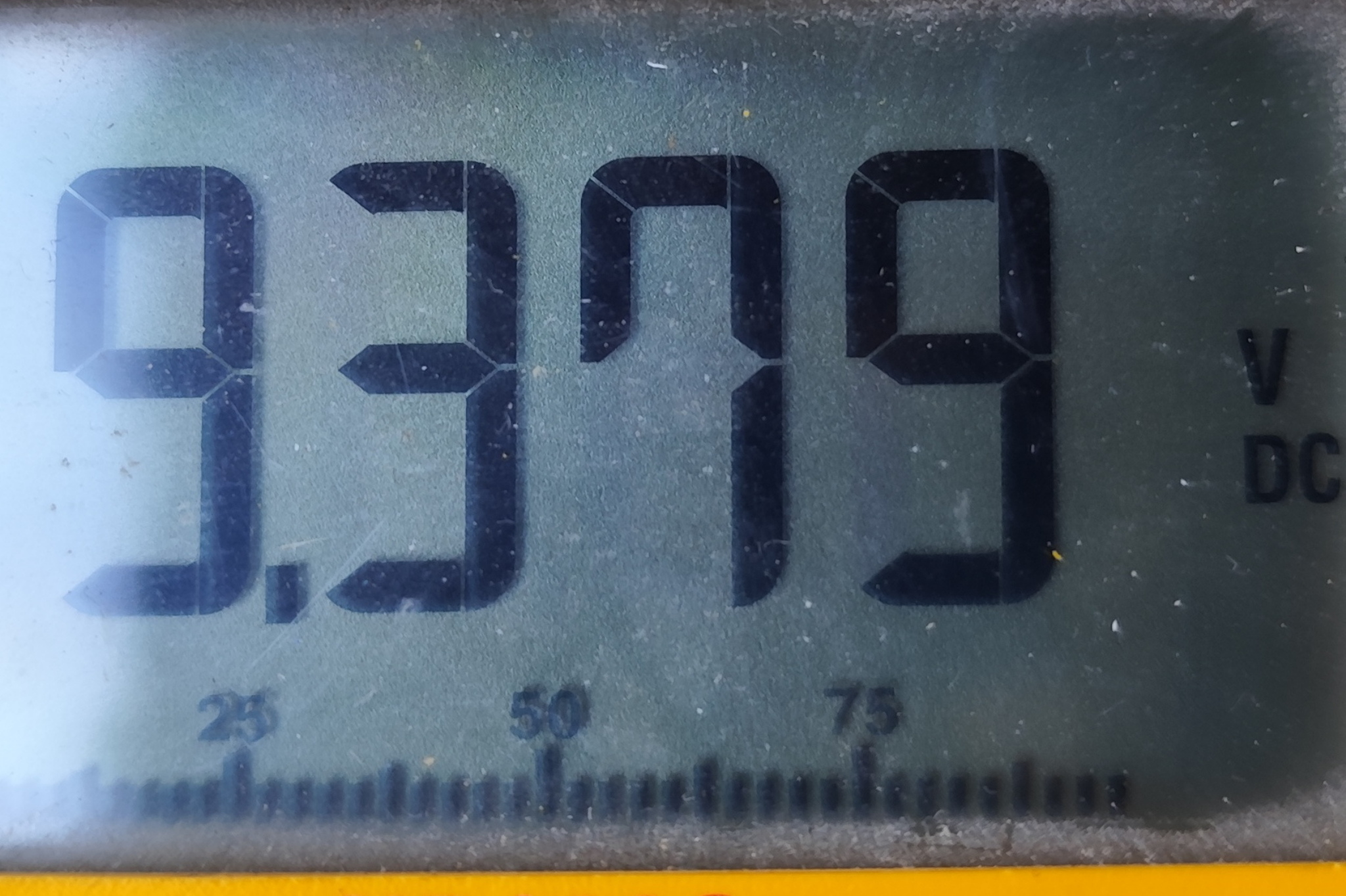
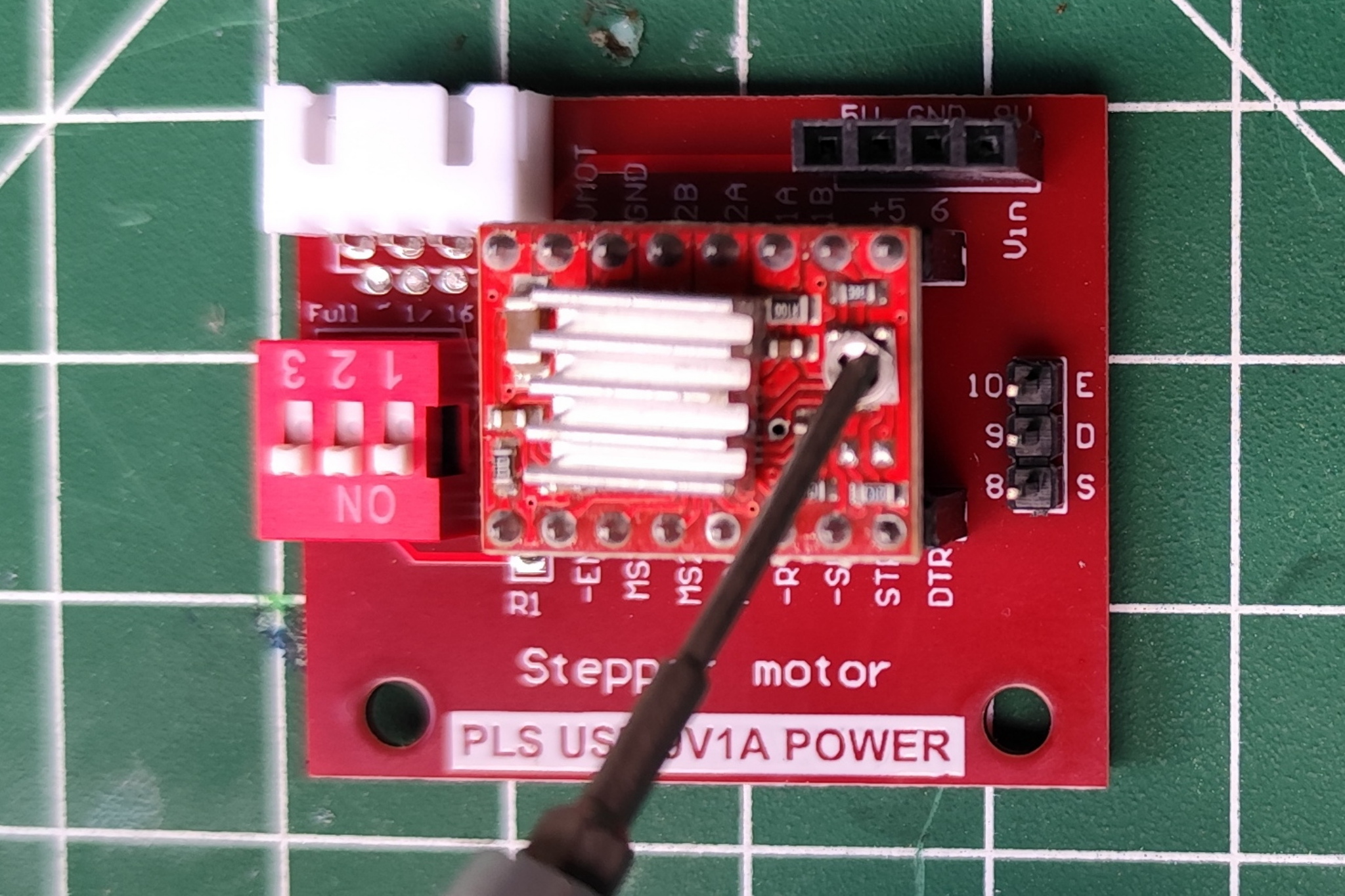
The board for the stepper driver is supplied with two different voltages, 5 V and 9 V. The voltage regulator must therefore be set first. To do this, the part is supplied with voltage via the USB port and measured on the output side. The voltage is changed using the blue potentiometer.
Das Board für den Steppertreiber wird mit zwei verschiedenen Spannungen versorgt, 5 V und 9 V. Also gilt es zuerst den Spannungsregler einzustellen. Dazu wird das Teil über den USB-Port mit Spannung versorgt und an der Ausgangsseite gemessen. Über den blauen Potentiometer wird die Spannung verändert.
Als Nächstes wird die VREF des Treibers eingestellt. In meinem Fall war das nicht nötig, weil die Treiber und Motoren aus meinem alten 3D Drucker stammen und somit schon eingestellt waren. Über den kleinen Potentiometer wird die Spannung passend zum Motor eingestellt. Wie hoch diese dann sein muss, erfährt man aus dem Datenblatt des Motors.
Als Nächstes wird die VREF des Treibers eingestellt. In meinem Fall war das nicht nötig, weil die Treiber und Motoren aus meinem alten 3D Drucker stammen und somit schon eingestellt waren. Über den kleinen Potentiometer wird die Spannung passend zum Motor eingestellt. Wie hoch diese dann sein muss, erfährt man aus dem Datenblatt des Motors.
I then soldered wires to the voltage regulator. Twice on the input side (5 V) to power the Arduino and the driver board and once on the output side (9 V) for the driver board. I secured the voltage regulator and the connections on the Arduino and the driver board with a hot glue gun to prevent them from coming loose unintentionally.
Ich habe dann Leitungen an den Spannungsregler gelötet. Zweimal auf der Eingangsseite (5 V) zur Stromversorgung des Arduino und des Treiberboards und einmal auf der Ausgangsseite (9 V) für das Treiberboard. Den Spannungsregler und die Anschlüsse am Arduino und dem Treiberboard habe ich mit der Heißklebepistole gegen unbeabsichtigtes lösen gesichert.
Step Five - Test Run
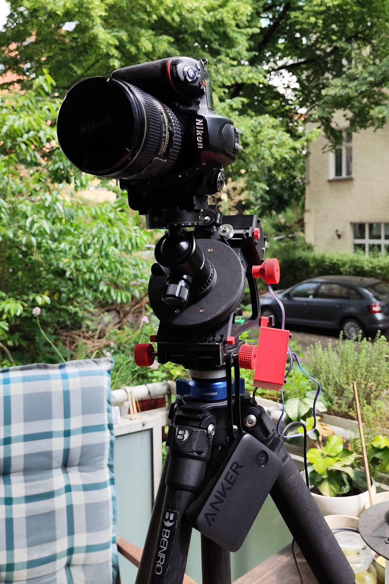
When everything was assembled, I did a first test run. I let the tracker run for 3 hours. During the 3 hours it turned 45°. So everything was fine. Now the weather just has to get better so that I can test it at night and hopefully show you the first pictures of the starry night sky soon. Rain and clouds are a real hindrance.
Als alles fertig montiert war machte ich dann einen ersten Testlauf. Ich ließ den Tracker 3 Stunden laufen. In den 3 Stunden drehte er sich um 45°. Also alles in Ordnung. Nun muss nur endlich das Wetter besser werden damit ich das dann nachts testen kann und euch hoffentlich bald die ersten Bilder des nächtlichen Sternenhimmels zeigen kann. Regen und Wolken sind da sehr hinderlich.

WHAT IS LIGHT PAINTING?
LICHTKUNSTFOTO
If you like my art visit www.lichtkunstfoto.de for more Light Art Photography and informations about Light Painting. Join me on Flickr Twitter

For more great Light Art Photography, Light Painting and inspiration check these light painters: 


WE ARE LIGHT PAINTERS
To help and support the LightPainters community here on Hive I would appreciate your delegation of HivePower. Any amount is appreciated. It does not require much to get started, we are happy for any gesture.

How to delegate?
Delegate 50HivePower, [50HP]
Delegate 250HivePower, [250HP]
Delegate 500HivePower, [500HP]
Delegate 1000HivePower, [1000HP]
All the Hive Power will help to upvote the artist's contribution as part of the LightPainters community.