Mira lo fácil que es construir una Lámpara de Colores con Arduino, y todo gracias al Curso de Robótica Educativa.

Saludos, querida comunidad amantes de la Tecnología, entusiastas y gente Geek, continuamos con la temática de Robótica Educativa con la plataforma Arduino, y en esta oportunidad los jóvenes del Núcleo de Robótica "Dr Aquiles Medina" realizaron una práctica con LED's RGB donde con su creatividad lograron construir Lámparas Luminosas de Colores.
Vamos con la teoría
¿QUE ES UN LED?
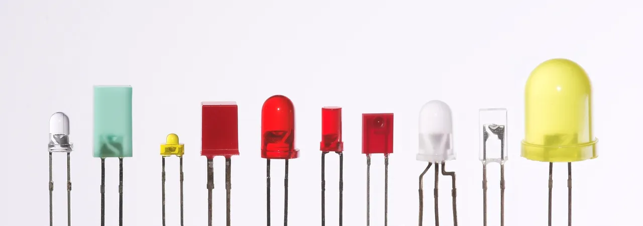
Un LED, (Light-Emitting Diode) como sus siglas en ingles lo indican es un diodo emisor de luz, en otras palabras es un componente que emite luz al ser atravesado por una corriente eléctrica, y estos los encontramos en casi todos los dispositivos electrónicos actuales.
Otra característica importante de un LED es que sólo dejan pasar la corriente en un sentido, por lo tanto tenemos que conectar correctamente el componente, eso quiere decir que tiene polaridad, la patilla más larga es la positiva (Ánodo) y la patilla mas corta es la negativa (Cátodo). En la siguiente imagen podemos apreciar su estructura y descripción.
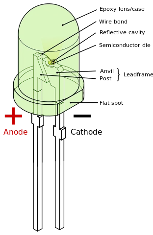
Author Mrubli, CC BY-SA 4.0, via Wikimedia Commons
Los valores más comunes de voltaje con los que trabaja un LED suelen estar entre 1.8 - 2.8 voltios, eso depende del color, brillo, tamaño. Sin embargo las tarjetas Arduinos trabajan con 5 voltios, por lo tanto para conectar un LED sin dañarlo se debe utilizar una resistencia para limitar la corriente suministrada al mismo y reducir el voltaje. Para realizar estos cálculos de la resistencia necesaria se utiliza la Ley de Ohm, pero en la mayoría de los ejercicios con Arduino es común utilizar resistencias entre 220 - 330 ohmios, colocando una resistencia para cada LED a encender.
El ejemplo básico para hacer parpadear un led con Arduino lo podemos simular con Tinkercad, y es el siguiente: Utilizando un LED rojo se conecta el cátodo al pin GND del Arduino, desde el pin 13 se conecta a la resistencia, y de la resistencia al ánodo del LED. También mostramos la programación básica para hacer funcionar el proyecto, solo falta hacer clic en el botón iniciar simulación y vemos funcionar el circuito.
 Arduino PARPADEAR LED por Oswaldo Hernández
Este es el ejemplo básico que podemos encontrar en la plataforma Arduino, así como en otros tutoriales en la web, si queremos conectar más leds, por ejemplo un led verde y otro amarillo , simplemente se agregan los leds y resistencias respectivos, y se conectan los pines adicionales del arduino, puede ser pin 12 y 11, se programa y listo.
Sin embargo estos LED's van a encender o emitir luz de manera individual cada uno, y los colores serán los mismos para cada uno de ellos: rojo, verde, amarillo. Si queremos generar colores de diferentes tonalidades, fucsia, rosado, morado, tornasol, azul cielo, anaranjado, morado, etc, tenemos que utilizar un LED RGB para combinar los colores.
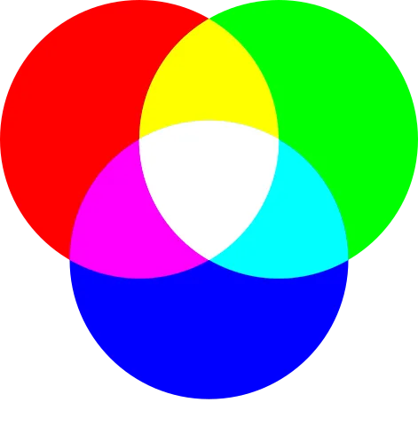
PALETA DE COLORES RGB
Author pd4u, CC0 WTF Public License, Version 2, via Wikimedia Commons
¿QUE ES UN LED RGB?
Un LED RGB (Red, Green, Blue), como lo indican sus siglas, son tres led en un solo encapsulado, es decir es un sólo LED que combina los colores Rojo, Verde y Azul y permite generar más de 16 millones de tonos de luz o colores.

LED RGB
Author XoxoXa3, CC BY-SA 2.0 DEED, via Wikimedia Commons
Este se compone de 4 pines:
- Pin 1: Led Rojo ( R - Vcc)
- Pin 2: Cátodo común (Gnd)
- Pin 3: Led Verde (G - Vcc)
- Pin 4: Led Azul (B - Vcc)
Para generar los colores se utiliza el principio de la mezcla aditiva de colores. Por ejemplo:
- Si encendemos el LED Rojo y Verde, obtenemos amarillo.
- Si encendemos el LED rojo y el LED azul obtenemos el color púrpura.
- Si encendemos el LED verde y el LED azul, obtenemos el color cian.
- Si encendemos los 3 colores LED's, con la misma intensidad, se obtendrá el color blanco.
Recomendamos ver el siguiente video para comprender el principio de Mezcla Aditiva
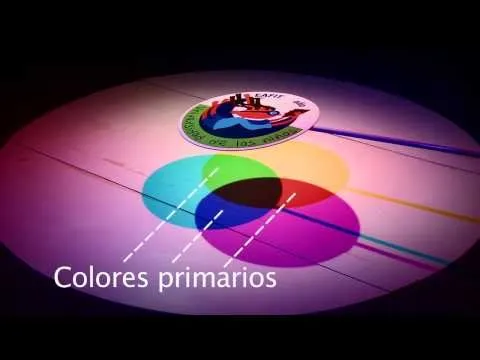 Mezcla Aditiva
Para generar diferentes tonos de colores con el LED RGB, en la programación se utilizan valores representados con números entre el 0 y 255, de esta forma para obtener el color rojo se pone el valor máximo del rojo y el valor mínimo de los otros colores: "R=255; G=0; B=0".
Ejemplos
- Rojo => R=255; G=0; B=0 => (255, 0, 0)
- Verde => R=0; G=255; B=0 => (0, 255, 0)
- Azul => R=0; G=0; B=255 => (0, 0, 255)
Veamos la siguiente tabla con los nombres de algunos colores básicos más utilizados en HTML y su equivalente en valor decimal RGB, estos mismos conceptos se aplican a los LED RGB.
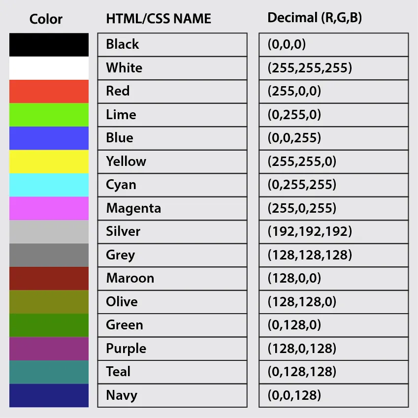 TABLA BÁSICA DE COLORES RGB
linuxhint
LAMPARA RGB CON ARDUINO
Entonces ya sabemos que utilizando un LED RGB, podemos crear un proyecto que nos permita generar diferentes tonalidades de colores, y de nuevo utilizando Tinkercad. Que necesitamos, una tarjeta Arduino, 3 resistencias de 220 ohmm, 1 LED RGB.
Identificamos los pines Red, Green, Blue y hacemos las conexiones hacia cada una de sus resistencias, y luego a los pines 9, 10, 11 del Arduino, seleccionando estos pines por tener capacidad para trabajar con pulso PWM. No debemos olvidar el pin negativo GND al cátodo del LED RGB. Listo, agregamos la programación respectiva y hacemos clic en el Botón Iniciar Simulación.
 Simulación con Tinkercad yArduino on LED RGB por Oswaldo Hernández
¿Y que paso con la Lámpara de Colores?
Aquí vamos. Luego de verificar que nuestro proyecto funciona bien en Tinkercad, realizamos los mismos pasos pero esta vez con la tarjeta Arduino y para dar ese efecto de lámpara de colores utilizamos una hoja de papel, formamos un tubo para la pantalla y encendemos nuestro proyecto.
A continuación se muestran diferentes imágenes de como se arma el proyecto y se ponen en funcionamiento las lámparas de colores por parte de los Jóvenes del Núcleo de Róbotica "Dr Aquiles Medina"
Programando el funcionamiento de las Lámparas en Arduino IDE


 |  |  |
|---|

Look how easy it is to build a Color Lamp with Arduino, all thanks to the Educational Robotics Course.
Greetings, dear community of Technology lovers, enthusiasts, and geeks, we continue with the theme of Educational Robotics using the Arduino platform. On this occasion, the youth from the Robotics Center "Dr. Aquiles Medina" carried out a practice with RGB LEDs, where with their creativity they managed to build Colorful Bright Lamps.
Let's go over the theory.
WHAT IS A LED?
A LED (Light-Emitting Diode), as the abbreviation in English suggests, is a light-emitting diode. In other words, it is a component that emits light when crossed by an electric current, and these are found in almost all current electronic devices.
Author Afrank99, CC BY-SA 2.0 via Wikimedia Commons
Another important characteristic of an LED is that it only allows current to pass in one direction, hence we have to connect the component correctly, meaning it has polarity. The longer pin is positive (Anode) and the shorter pin is negative (Cathode). In the following image, we can see its structure and description.
Author Mrubli, CC BY-SA 4.0, via Wikimedia Commons
The most common voltage values that an LED operates with are typically between 1.8-2.8 volts, depending on the color, brightness, size. However, Arduino boards work with 5 volts, so to connect an LED without damaging it, a resistor must be used to limit the current supplied and reduce the voltage. The necessary resistance calculations are done using Ohm's Law, but in most Arduino exercises, resistances between 220-330 ohms are commonly used, placing one resistor for each LED to be turned on.
The basic example to make a LED blink with Arduino can be simulated using Tinkercad, as follows: Using a red LED, connect the cathode to the Arduino's GND pin, connect from pin 13 to the resistor, and from the resistor to the LED's anode. Additionally, the basic programming to run the project is shown, just click the start simulation button and see the circuit in action.
Blinking LED with Arduino by Oswaldo Hernández
This is the basic example found on the Arduino platform, as well as in other tutorials on the web. If we want to connect more LEDs, for example, a green LED and a yellow one, simply add the respective LEDs and resistors, connect to additional Arduino pins, perhaps pin 12 and 11, program it, and you're set. However, these LEDs will light up individually, each emitting the same colors: red, green, yellow. If different shades of colors are desired, such as fuchsia, pink, purple, iridescent, sky blue, orange, purple, etc., an RGB LED must be used to combine colors.
RGB Color Palette
Author pd4u, CC0 WTF Public License, Version 2, via Wikimedia Commons
WHAT IS AN RGB LED?
An RGB LED (Red, Green, Blue), as its initials indicate, are three LEDs in a single package. It is a single LED that combines the colors Red, Green, and Blue, allowing for more than 16 million shades of light or colors.
RGB LED
Author XoxoXa3, CC BY-SA 2.0 DEED, via Wikimedia Commons
It consists of 4 pins:
- Pin 1: Red Led (R - Vcc)
- Pin 2: Common Cathode (Gnd)
- Pin 3: Green Led (G - Vcc)
- Pin 4: Blue Led (B - Vcc)
To generate colors, the principle of additive color mixing is used. For example:
- If we turn on the Red and Green LEDs, we get yellow.
- If we turn on the Red and Blue LEDs, we get the color purple.
- If we turn on the Green and Blue LEDs, we get the color cyan.
- If all 3 color LEDs are turned on with the same intensity, white color is achieved.
We recommend watching the following video to understand the principle of Additive Mixing
Additive Mixing
To generate different shades of colors with the RGB LED, programming uses values represented as numbers between 0 and 255; thus, to obtain the color red, the maximum value for red is used along with the minimum value for the other colors: "R=255; G=0; B=0".
Examples
- Red => R=255; G=0; B=0 => (255, 0, 0)
- Green => R=0; G=255; B=0 => (0, 255, 0)
- Blue => R=0; G=0; B=255 => (0, 0, 255)
Let's see the following table with the names of some basic colors most used in HTML and their equivalent in decimal RGB value; these same concepts are applied to RGB LEDs.
BASIC RGB COLOR TABLE
linuxhint
RGB LAMP WITH ARDUINO
So now we know that by using an RGB LED, we can create a project that allows us to generate different color shades, again using Tinkercad. What do we need? An Arduino board, 3 220 ohm resistors, 1 RGB LED.
We identify the Red, Green, Blue pins and make connections to each of their resistors, and then to pins 9, 10, 11 of the Arduino, selecting these pins for their ability to work with PWM. We must not forget to connect the negative GND pin to the cathode of the RGB LED. Ready, we add the respective programming and click on the Start Simulation button.
Simulation with Tinkercad and Arduino on RGB LED by Oswaldo HernándezWhat Happened to the Color Lamps?
Here we go. After verifying that our project works fine in Tinkercad, we follow the same steps but this time with the Arduino board, and to achieve that color lamp effect, we use a paper sheet, form a tube for the screen, and turn on our project.
Below are different images showing how to assemble the project and how the color lamps operate by the Robotics Youth Team "Dr. Aquiles Medina"
Programming the operation of the Lamps in Arduino IDE
| | |
|---|
Fuentes / Sources
- Imágenes de mi autoria.
- Capturas de pantalla con https://www.veed.io/
- Translated and formatted with Hive Translator by @noakmilo.