Usually usb sticks have an internal led which is used to check when it is plugged and when data is being transfered it starts blinking. However its brightness coulde be relatively low and thus it would be nice to improve its brightness features in order to improve the experience with Blinkit and never miss again a notification. For this reason this tutorial will be very benefitial to Blinkit project as the replacement of the existing led with a more powerful one will significantly enhance brightness.
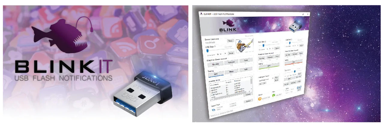
What is Binkit?
Blinkit can blink a USB stick led and blink smart lamp's on Steem related actions.
What Will I Learn?
- Desolder the smd led of a USB stick
- Solder a brighter and bigger LED in place of the smd LED
- How to do this in a safe way
Requirements
- USB stick
- Digital multimeter
- Soldering iron
- Soldering paste
- Soldering wire
- Wire cutter
- Tweezers
- 5mm Standard LED
- Hot Glue
Difficulty
- Basic: Soldering skills
- Basic Electronics skills
Tutorial Contents
Today we will start our journey with the Blinkit Project, made by @techtek, where he asked me to look into "How to safely, modify the LED of any USB stick" one of the possible upgrades is to make the LED more bright and here started my journey on how to upgrade a USB stick's LED to a brighter one.
You know, that tiny LED (smd LED) we find in most USB sticks that lights up when we transfer data to it?
With this tutorial and Blinkit you can make your USB stick blink much brighter, with just a few simple steps.
Let's start with our DIY tutorial...
Before implementing the steps we must chose the right LED and the right setup in order not to damage the USB by burning some connections inside the chip. For this reason we must know that most common LED’s require a forward operating voltage of between approximately 1.2 to 3.6 volts with a forward current rating of about 10 to 30 mA, with 12 to 20 mA being the most common range. In most cases LEDs are operated from a low voltage DC supply, with a series resistor, used to limit the forward current to a safe value. Here's a schematic on how the connections should be made and an explanation on how much should be the value of the current limiting resistor in order to operate on a safe side (i have chosen 10mA to be on the safe side which is in the range of smd led current draw)

Both the forward operating voltage and forward current are proportional and vary depending on the semiconductor material used but the point where conduction begins and light is produced is about 1.2V for a standard red LED to about 3.6V for a blue LED. This is why the choice of the LED for this DIY project requires some easy but needed setup in order not to damage the USB stick's hardware.
DIY Tutorial
Step 1
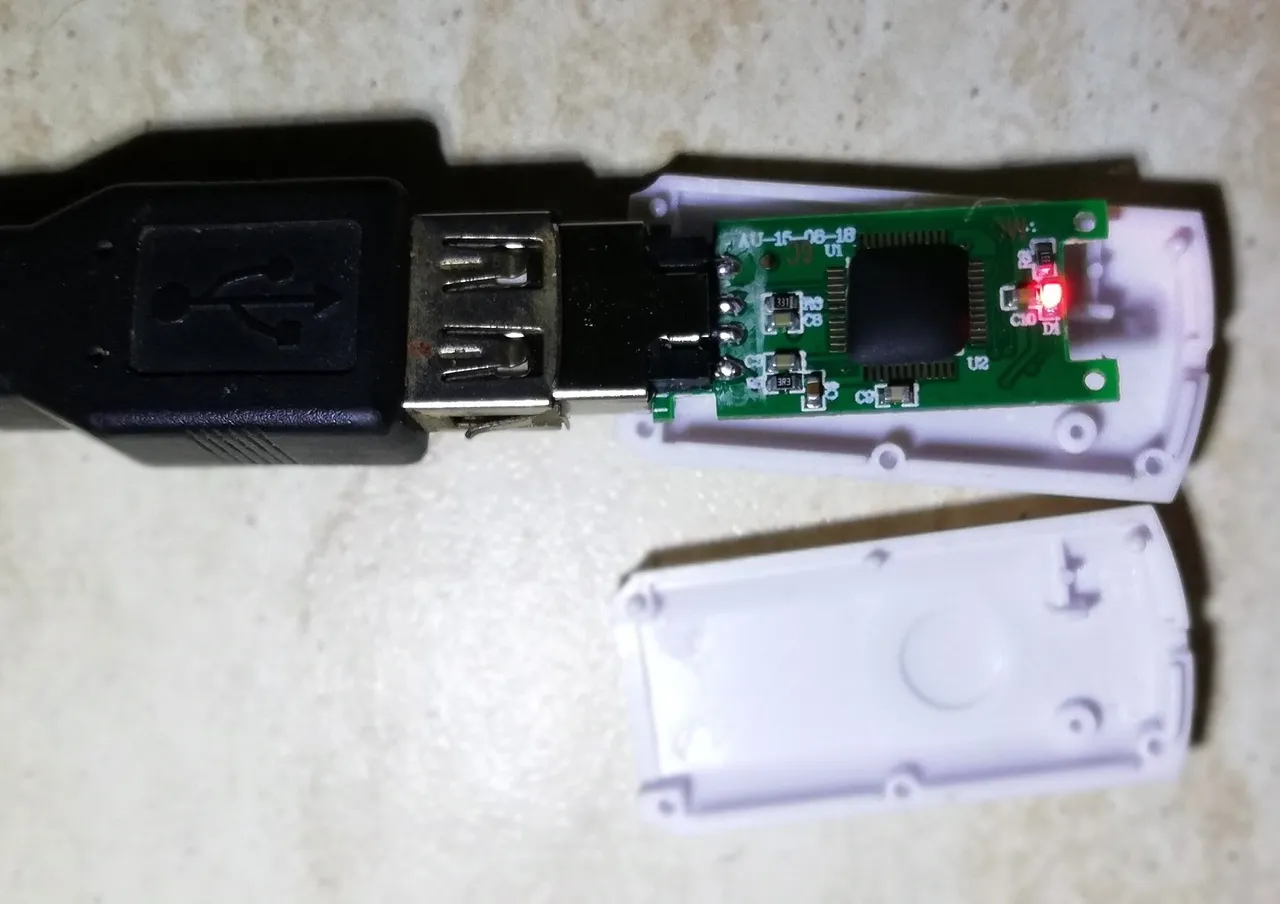
Open your USB housing in order to have access to its circuit, most of the time it can be easy opened by sliding something in between the housing, and twisting it open.
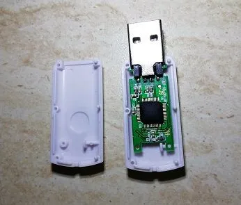
Step 2
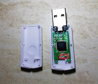
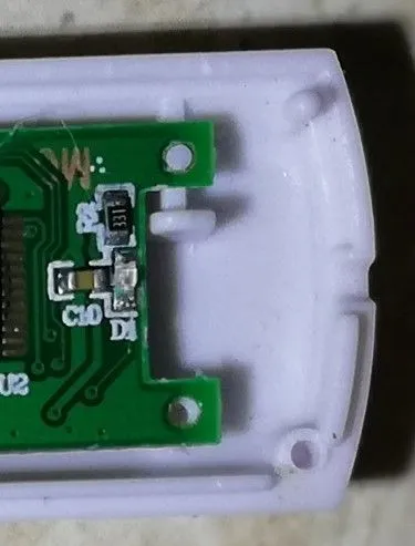
Locate the smd LED and its relative current limiting resistor.
(normally it should be around 330 Ohm which you will se written as 331 on the smd resistor)
Step 3
Attach the USB sticks PCB to a USB socket in order to let it light up.
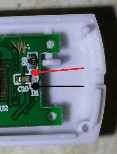
Step 4
While the USB stick is attached and the led is ON, use the digital multimeter to locate the Cathode (-) and the Anode (+) of the smd LED, then also measure the voltage (VS) across resistor and led and take note of it (in my case it was around 3,6V). You can now detach the USB stick from the USB port and do your calculations (using Ohm's law, see image below) to determine the series resistor to use knowing that the forward current we have chosen (IF) is 10mA and knowing the forward voltage drop across each type of LED (image below in the table).

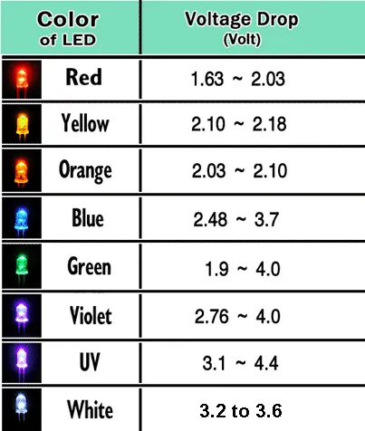
Since the voltage VS i measured on my USB stick was 3,6V, which is in the range of the forward voltage drop of the WHITE LED, using Ohm's Law, I can replace the existing led with a standard white led and do not necessarily require a current limiting resistor. If in a situation VS=6.6V i was to use a Red led for example which has a voltage drop around VF=2V i would require a 460 Ohm Resistor to keep current limited to 10mA.
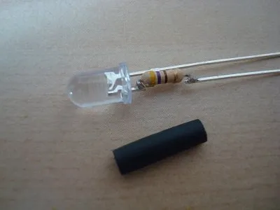
In that case this would be my setup for the LED (image below). The resistor will be placed on the anode of the led.
Step 5
Paying attention not to heat up too much the circuit to avoid damaging the USB, use the soldering iron and the tweezers to desolder/remove the smd LED from the circuit along with its resistor (putting some soldering paste on the two components before desoldering will help removing them quite easily) then short the 2 pins on the pcb where the smd resistor was located
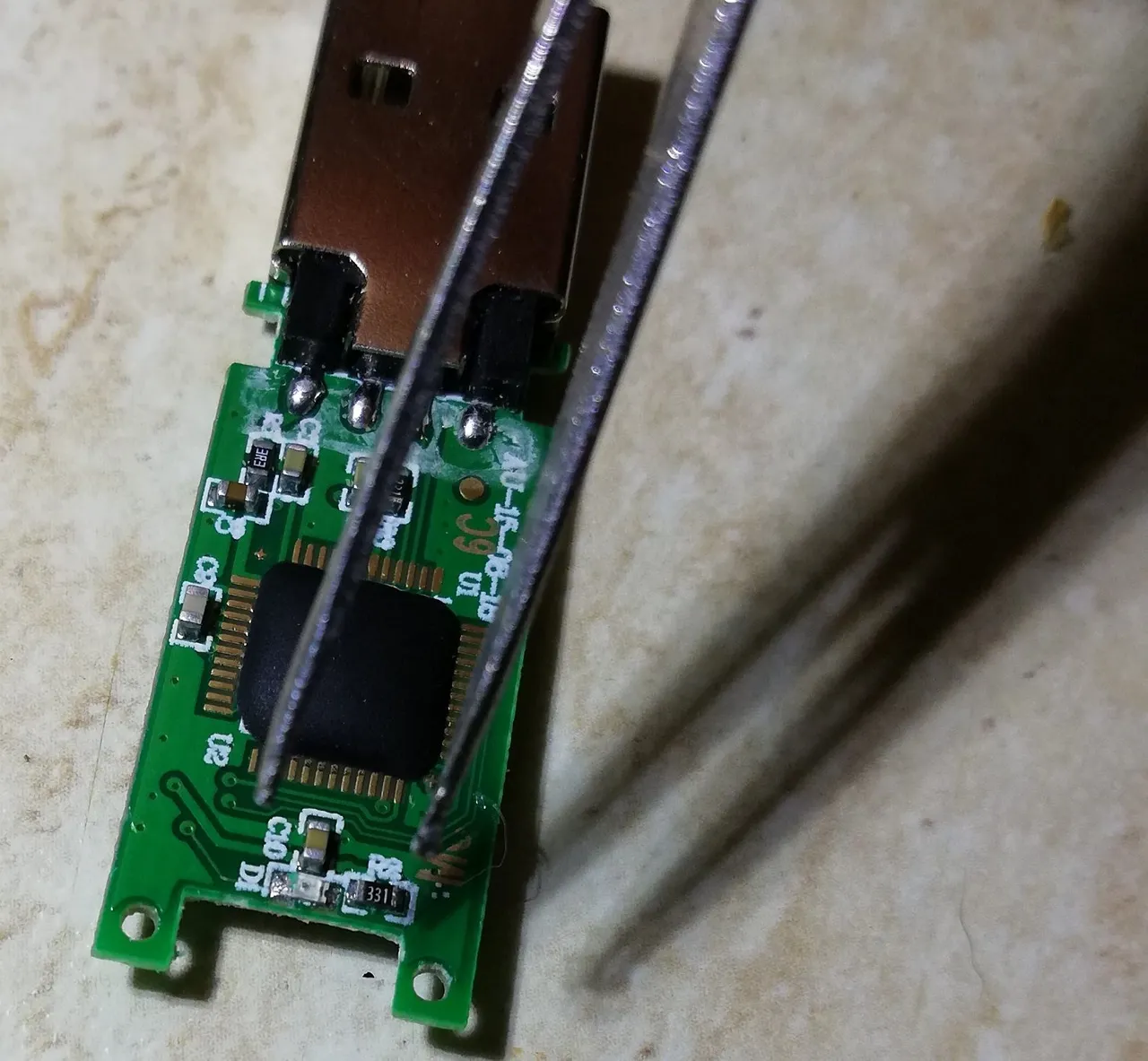
Step 6
With the help of a cutter or with the tip of the soldering iron or 5mm drill make a hole on the bottom of the USB housing to let the new 5mm LED fit well while the housing is closed.
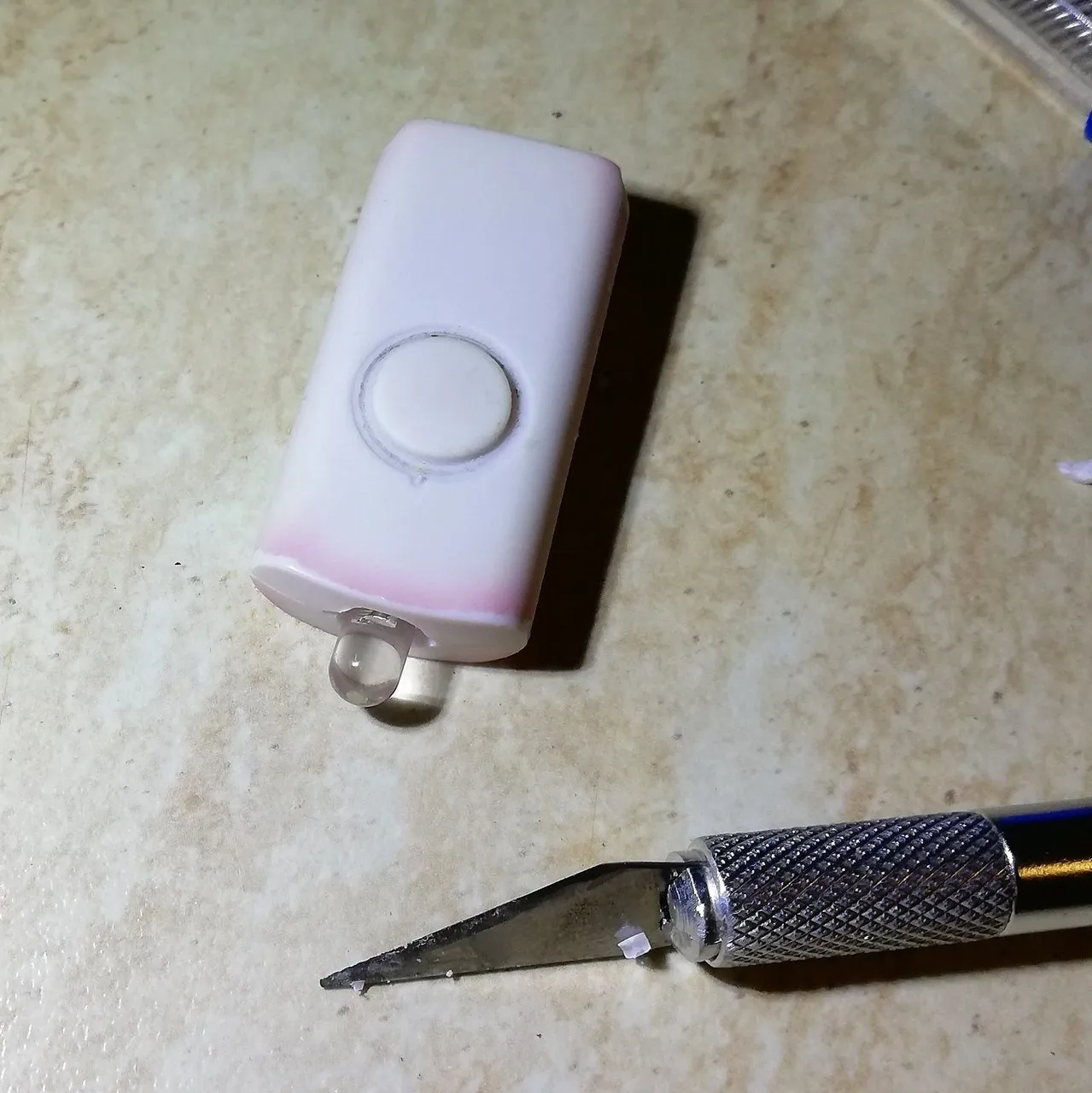
Step 7
Take the right measures and trim the leads of the new 5mm led in order to regulate the location of the LED (i have chosen to have its LED partly out of the housing as i have found to be somehow more powerful but you could fit the entire LED inside if there is enought space inside the housing.)
Step 8
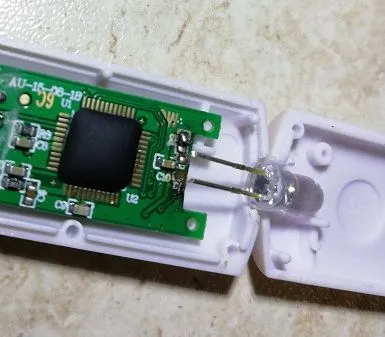
Finally localize the Anode and Cathode of the 5mm LED and solder the LED on the pcb where the previous smd led was located (pay attention not to stress too much with the soldering iron as the connection on the pcb are very small thus fragile when exposed to too much heat and for a long time)
Step 9
With the use of some hot glue you will be able to give some good stability to the USB in the housing and fix it to the pcb from inside and avoid some internal damages due to the detaching of the pcb connections.
Step 10
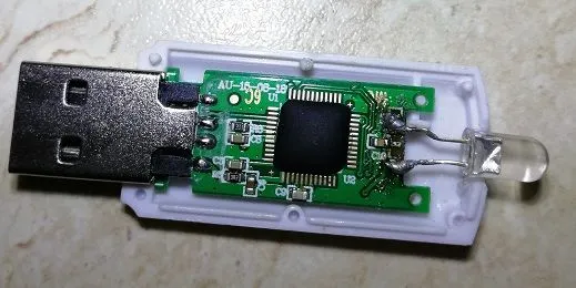
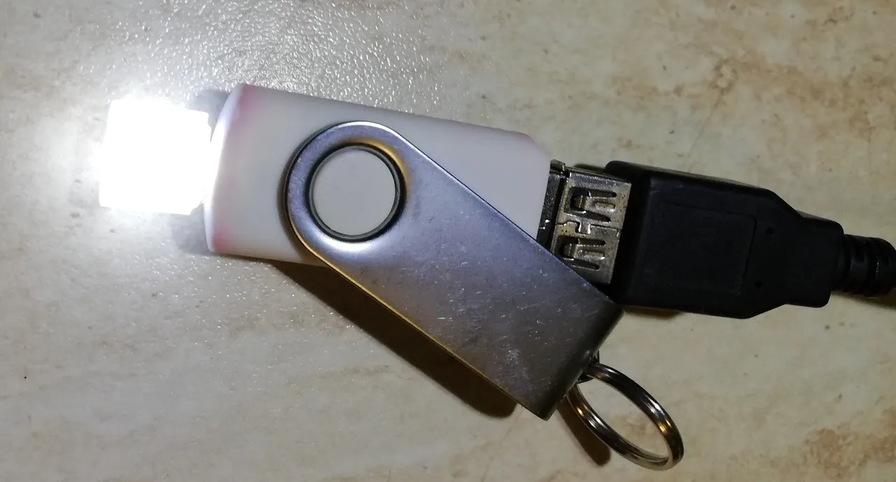
Close the housing and connect the USB stick to double check if everything is working fine.
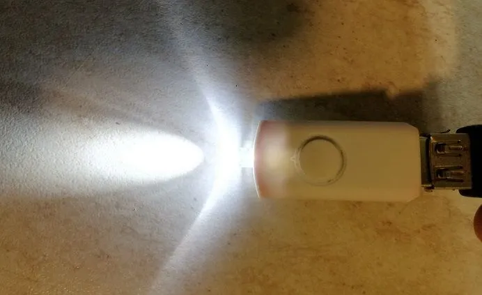
The job is finished and now your old USB stick is ready for a improved Blinkit experience and thus ready to blink with the new LED which will provide a much stronger light.

Optional modification:
Step 11
If you would like a more homogene distribution of the light you could cut a small piece of the hot glue stick and drill a small hole inside it without passing from edge to edge and use it as a cap of your LED. It will make the light look more elegant and will let you notice all the incoming notifications.
JOB DONE AND READY TO START BLINKING THE LED WITH BLINKIT !!
This tutorial could help you to improve the LED of your USB stick and improve the functionality of Blinkit. Other modification and Tutorials will be made, and made available soon. With new DIY projects to let you enjoy led light notifications!
LET'S MAKE THE WORLD BLINK WITH BLINKIT!
Posted on Utopian.io - Rewarding Open Source Contributors