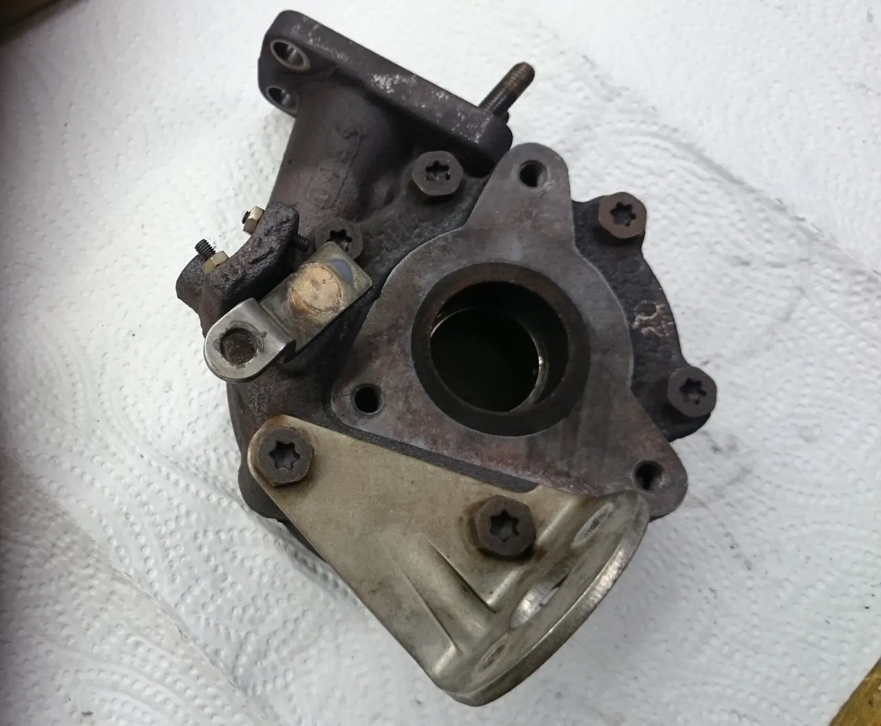
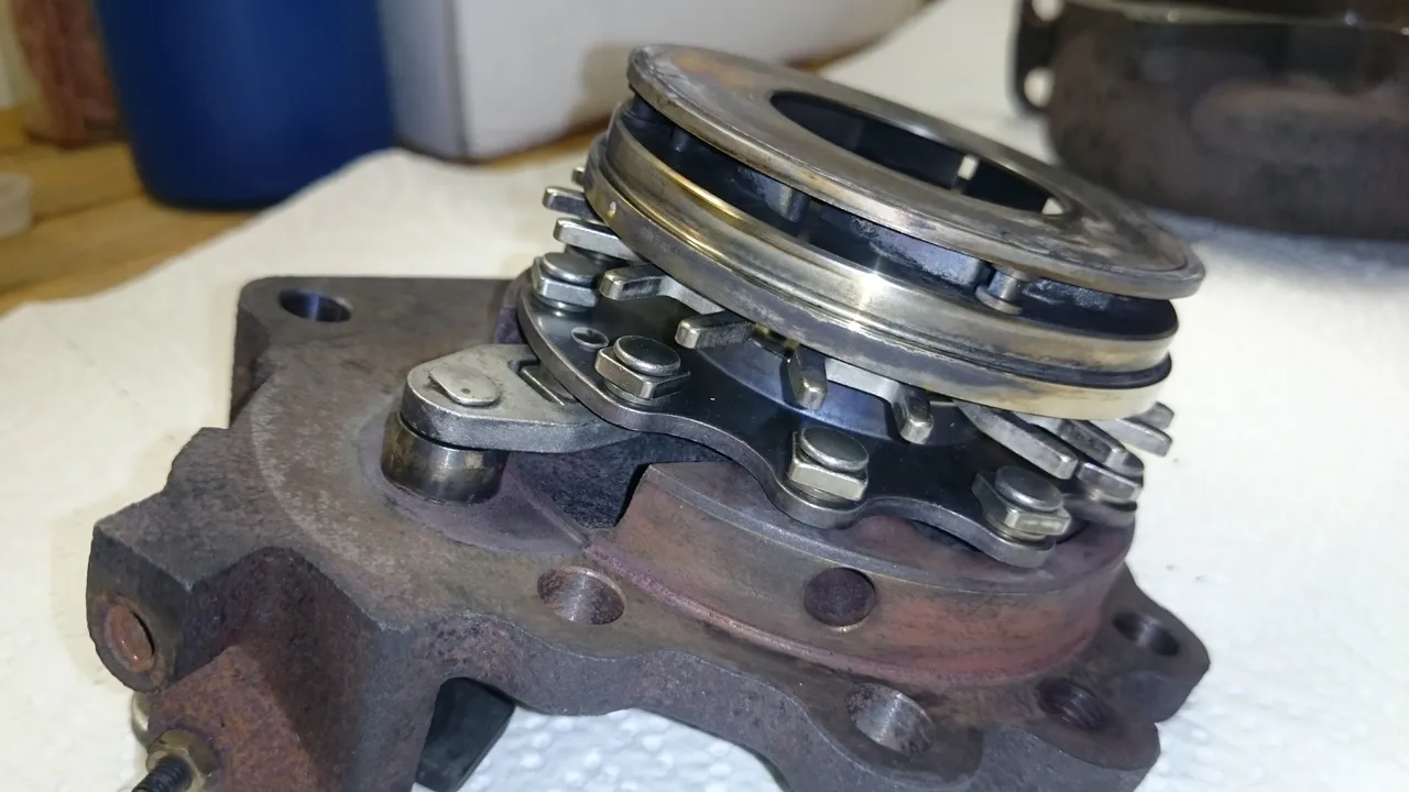
Image #1: Disassembled turbine section (already cleaned).
Hello Steemians! I'm back with a post on some real hardware. What you see above is the variable-geometry part of my car's turbocharger assembly. I had to take it apart because for the last 4 days the car didn't have any power anymore - and while I was reassembling this part I thought some of you might be interested.
Ok, moar details: My car is powered by a 1.4l 16V HDI diesel engine (DV4TED4) with 66kW. The exact model of the turbocharger:
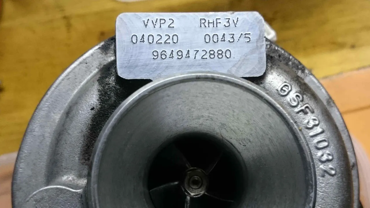
Image #2: Part Numbers
Disassembly was a pain by the way. WD-40, large levers and careful use of a rubber hammer did the trick though.
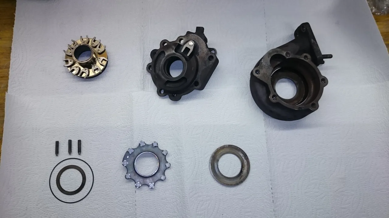
To make sure you know what I am talking about (ok, also simply because I love the pictures) I will try to give the parts names. Try because with most of them I'm not sure what to call them...
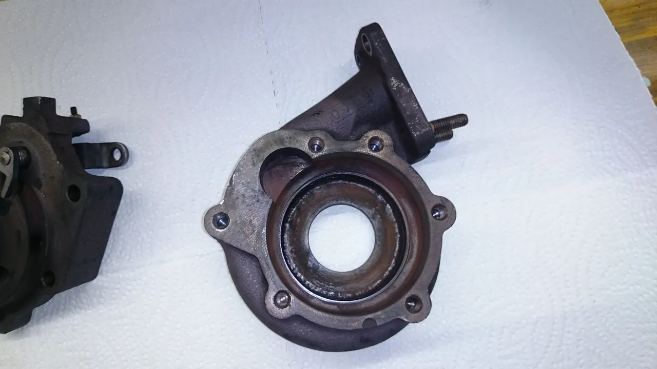
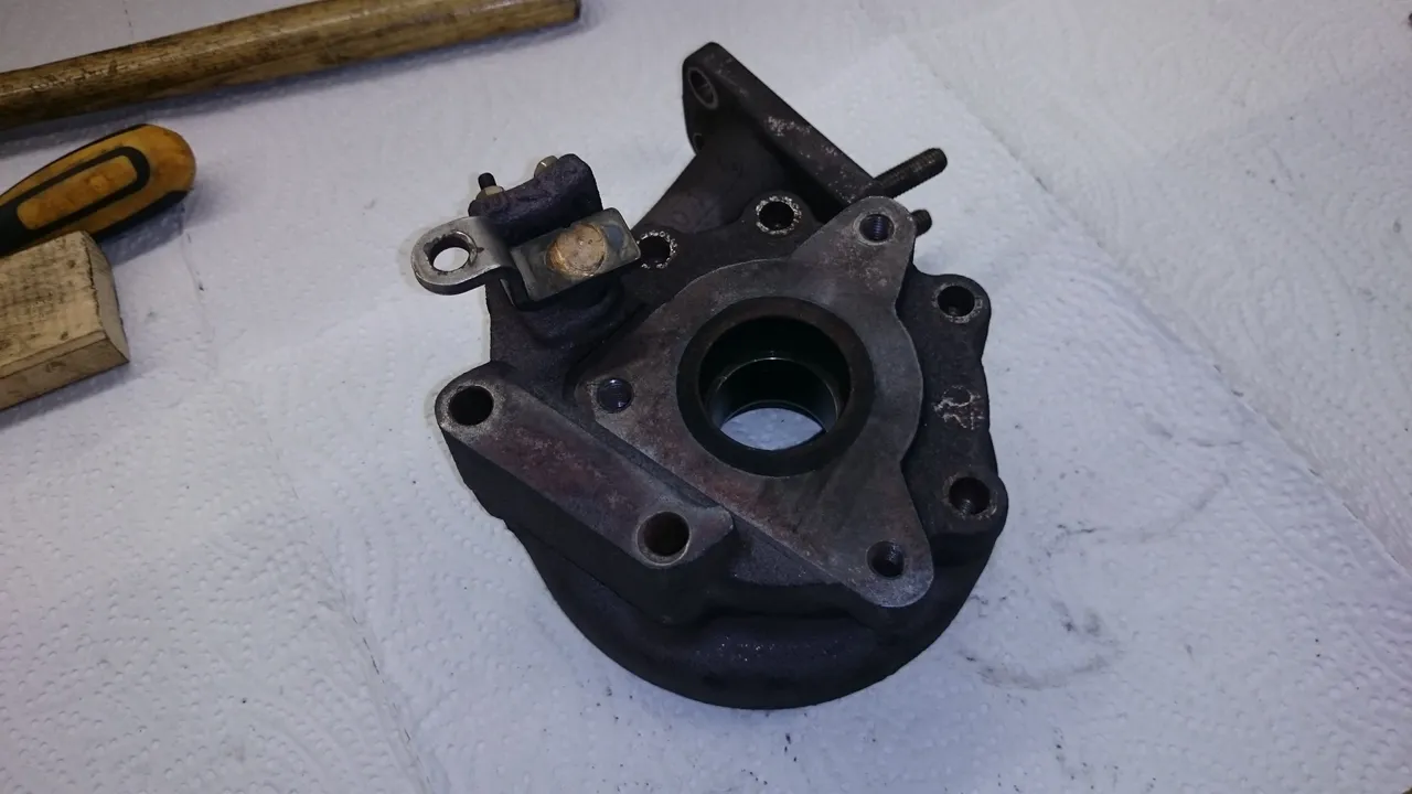
Image #3: Turbine casing
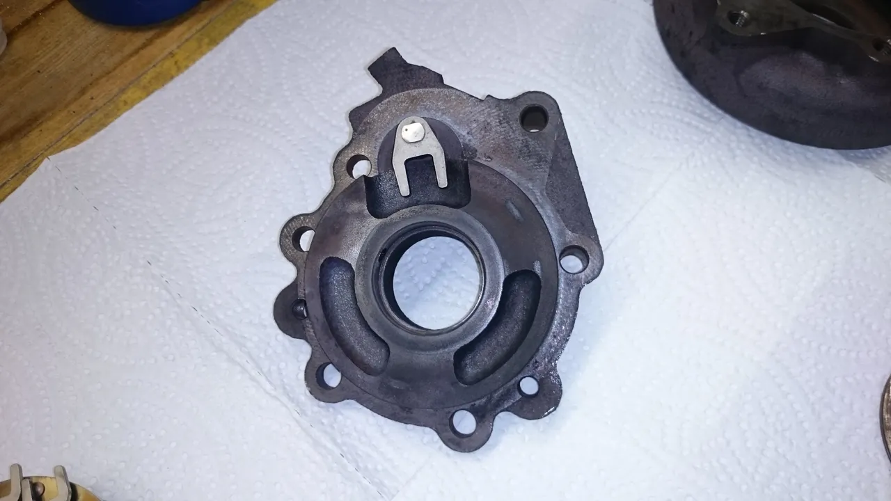
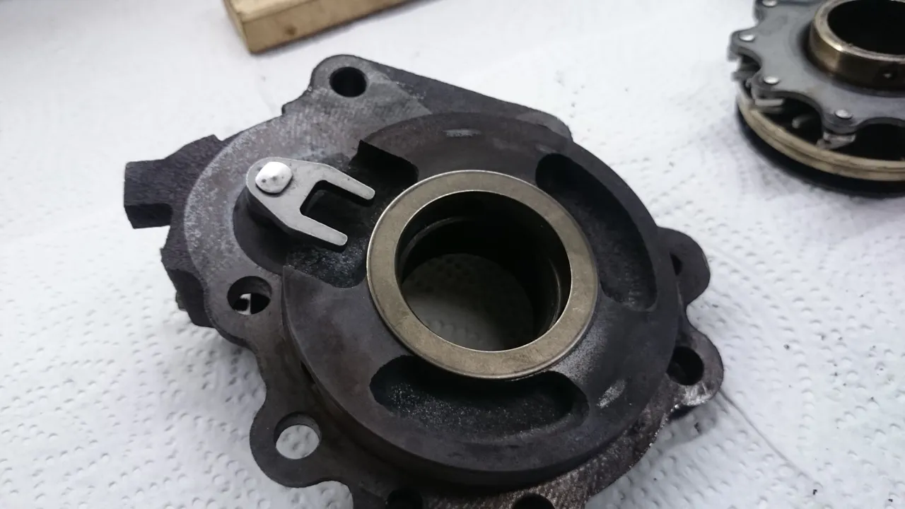
Image #4: Back wall of turbine casing
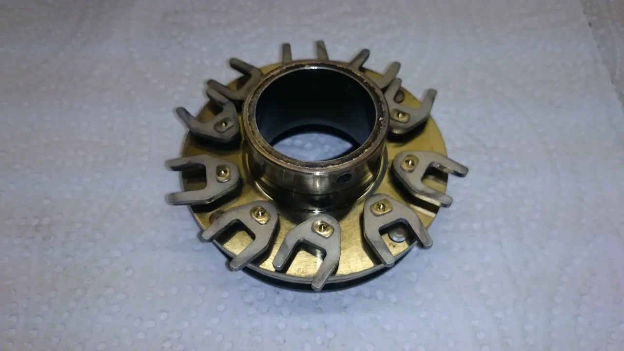
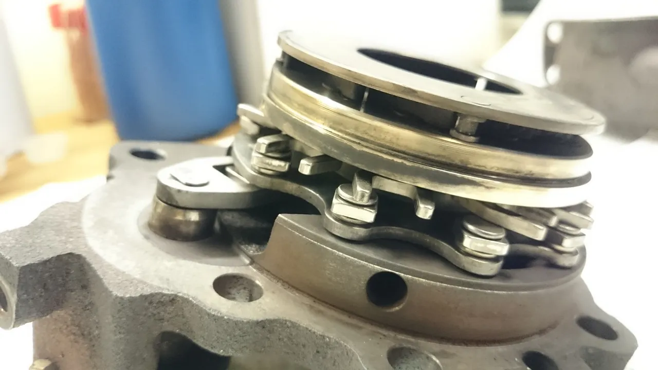
Image #5: Variable-vane assembly (cannot be disassembled further)
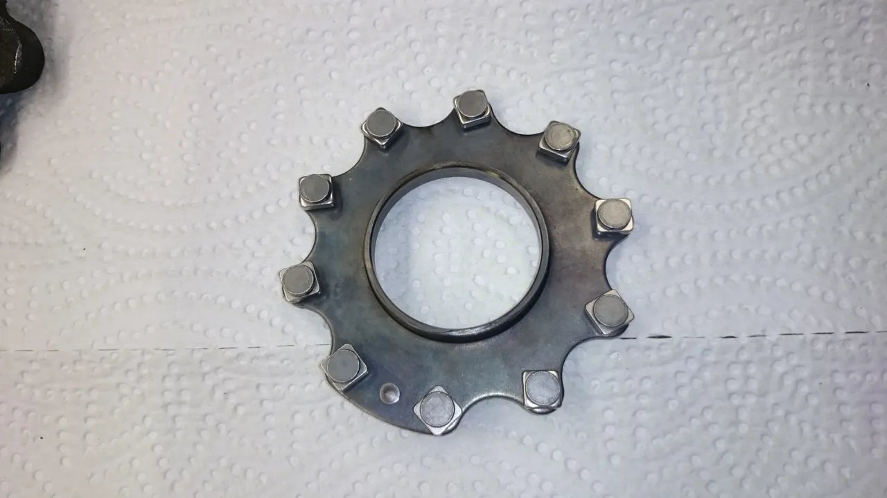
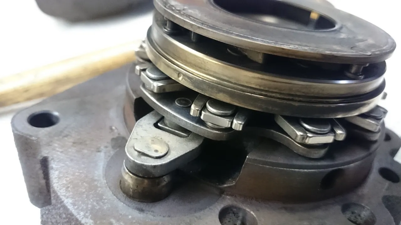
Image #6: Conveyor cog
Assembling
Place spacer on back wall of turbine casing. (I actually forgot this the first time around and had to disassemble it all over again ;)
Put the conveyor cog on top of the spacer and make sure it is properly connected to the manipulator arm. Don't worry about the orientation of the small squares yet, but do make sure the spacer underneath stays in place.

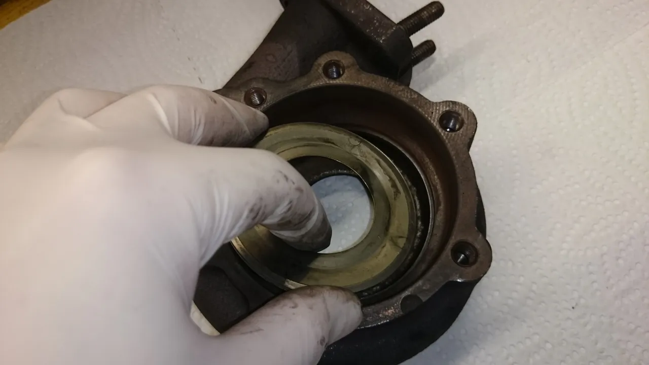
Carefully insert the variable-vane assembly into what we just built. Note the small indentation on the rim of the vane assembly. This small dot needs to be line up with the large actuator arm as good as possible. In my case the assembly would only go down a millimeter or so before it got stuck. If the same happens to you use a rubber hammer and a piece of wood to gently nudge it down until it is sitting on top of the conveyor cog. I found it most efficient and also least harmful for the delicate assembly to make use of the small step that goes all around the part.

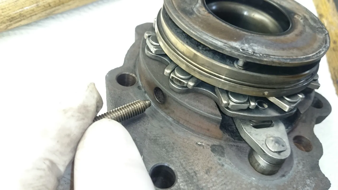
Now it gets a bit fidgety. In an iterative process adjust the vanes and squares to they fit everywhere, then use the hammer to bring the parts closer together. After a small movement stop hammering and go back to making sure the delicate vane-guides have not been moving too much. Finally all the guides should line up with all the small squares like this:
As soon as the vane assembly is down all the way look into one of the three screw holes and make sure the rotatory orientation is correct. Then insert the three screws and gently fix them. A little torque won't hurt, just don't overdo it.
At this point everything will be held together by the screws, so we can play with the mechanism and see how it works. What my hand is doing in the video below would normally be controlled over a clever pressure-regulation system that ensures the best possible turbo speed at any given motor load. Turning the vanes changes the angle between the incoming gas and the turbine, thus effectively regulating the amount of mechanical power the turbine can generate. Clever!

Now the last two seals are put into place, then the two halves of the turbine casing can be closed up.

Finally we put the screws in and fix them with a lot of torque and you're done with this bit of the turbo.