Greetings steemians!
Its another week again and i wish you all the best in it.
I don’t think there’s any better suiting relieve as having to use something and it never finishes. That is the direction we have already headed but we are advancing daily in the area of power generation. The use of conventional methods like steam power generation, which still remains the largest source of electricity in the world is detrimental to our ecosystem.
The extent of global warming has been alarming in recent years. This is due to the burning of fossils like coal (the chief cause), natural gases, and fuel oil and so on. Nuclear power is another scheme with substantial results. However, the health risks associated with the use of radioisotopes is one great limitation.
It is therefore important for us to find means of generating power without causing harm to Mother Nature or better still reduce the harm caused.
The use of renewable sources like wind, solar, hydro, geothermal etc. is not new today. In fact, advancement in these areas of power generation is increasing by the day. Hydropower (power derived from water in motion or at an elevated height) has been around since ancient times, where it is used for irrigation purposes and powering of some mechanical devices.
Today, the most important application of hydropower is in the area of power generation, with hydroelectricity taking the largest share in the total power produced from renewable sources.
In this article today, I will be discussing about Hydroelectricity. We begin by looking at the devices which are used to extract energy from water – the hydraulic turbines. We will later then discuss a simple hydroelectric power plant, and then highlight some advantages and also see if they have any shortcomings or not.

HYDRAULIC TURBINE

Generally, turbines are devices that extract energy from fluids (liquid or gas). The field of hydraulics deal with the use of liquid and thus we can easily deduce what the function of a hydraulic turbine is. Notwithstanding, I still feel like stating it.
Hydraulic turbines are devices that are used to extract power from liquids, usually water. They have runners with blades attached to them. The action of the moving stream of liquid on this blades displaces these blades which in turn impart rotation on the runner.
The runner is connected to a shaft which in turn is coupled with a generator that produces electricity. I gave an overview of the essential element needed to generate electricity by electromagnetic induction in my post on Steam Power generation. The only difference here is that in steam power generation, the prime movers (the source of rotation) are steam turbines but in this case it is the Hydraulic turbine.
Turbines generally, are of two kinds – Impulse and Reaction type.
The simple distinction between this two is that, while conversion of pressure head into velocity head takes place completely before getting to the turbine blades in the impulse turbine, this conversion occurs throughout the interaction of the fluid with the blades in a reaction turbine.
Having said this, we can now talk about the types of hydraulic turbines. There are different variations of hydraulic turbines which all can either be an Impulse type or a reaction type. We shall look at an impulse hydraulic turbine called the Pelton wheel as well as a reaction type called the Francis turbine. There’s another reaction type turbine, which is the Kaplan turbine but I don’t want to make this article a lengthy one.
PELTON WHEEL TURBINE

The Pelton wheel as shown in the image to the right consist of large diameter runner with series of elliptical shaped blades often called buckets attached to it. The runner is connected to a shaft which is in turn connected to an electric generator.
The pelton wheel turbine also consist of a nozzle attached to the exit of a long large diameter pipe often called the penstock. The work of the nozzle is to convert the available pressure energy into kinetic energy. It does this based on the Bernoulli’s Principle. The penstock is always connected to a large reservoir or dam at with the inlet is at an elevated height to give enough head – Pressure head.
Let me explain this pressure head a bit for the sake of the uninitiated.
When you have a liquid, say water in a vertical drum, the pressure exerted at any point in the drum is given by:
P = ρgh
(where ρ = density of the liquid, g = gravitational acceleration, = height at that point from the upper surface of the liquid).
This implies that, the lower a point is in the tank, the higher the pressure felt at that point. This is due to the fact that more volume of the liquid will lie above it and thus exert more force on it.
No one can tell me that the water storage tank in his house is located on the ground level. Everyone installs the tank at the top of the house so that the exit of various taps is well below the upper surface of water in the tank to give enough head.
Its (pelton wheel) operation is simple – Water rushes down the penstock and through the nozzle the pressure energy is converted into kinetic energy (energy in form of velocity). The water exit this nozzle as a high velocity jet and strikes the buckets attached to the runner. Consequently, motion is induced in the runner and hence the turbine shaft.
This turbine was invented and patented by L. A. in 1889 and hence the name pelton wheel. It is only suitable in applications where a very high head is available.
FRANCIS TURBINE
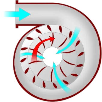
In cases where there is relatively less pressure head, the Francis turbines are suitable. These types of turbines have a spiral volute casing as shown in the image to the left. They have two sets of blades – the guide vanes and the rotor blades. The guide vanes are employed to direct the flow of water in the right direction before they encounter the rotor blades.
The conversion of pressure head takes place a little bit during the encounter of the fluid with the guide vanes but the major conversion takes places around the rotor blades. This conversion occurs gradually as the fluid flow past the rotor blades. Both sets of blades usually have a hydrofoil cross-section (a hydrofoil is a streamlined body that moves in liquid, such that losses are minimized. Its equivalent is an airfoil in the case of air flow).
Through this conversion, kinetic energy is delivered to the rotor which by now you should know is connected to a shaft. Hence, rotation is induced in the shaft.
Always remember that in all cases, our aim is to produce this rotational motion to drive an electric generator.
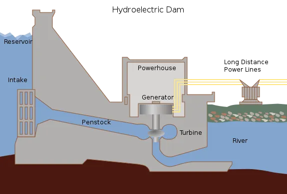
SIMPLE SETUP OF HYDRO-ELECTRIC POWER PLANT
At this point you should note that most hydroelectricity stations utilize the Francis Turbine
The following are the notable components that makes up a hydroelectric power station. I will explain each of this component while also discussing the operation of the power plant.
- Dam
- Penstock
- Hydraulic Turbine
- Electric Generator
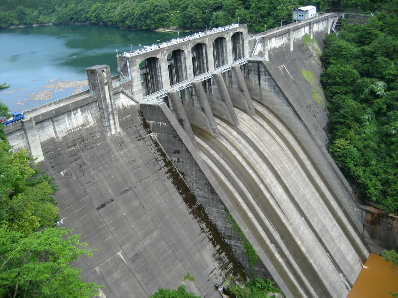
The Dam (see the first image at the top) is a large impoundment of water. It is like building a wall in the path of a stream. Consequently the water level will rise, which then produces enough Pressure head. The Penstock which is a large diameter pipe is connected to this large reservoir and its function is to transport water to the hydraulic turbine (I think justice have been served here). When the water hits the hydraulic turbine blades, rotational motion is induced in the turbine shaft.
The rotating shaft is connected to an electric generator, which produces electricity via electromagnetic induction.
The difference in height between the inlet and outlet of the penstock is the pressure head needed. Also the larger the pipe, the more the flow rate.
POWER AND OVERALL EFFICENCY OF THE HYDRAULIC TURBINE
At this point is it necessary to introduce to you the expression for calculating the power supplied to the turbine. This is given by:
Power = ρghQ
Where Q = Volumetric flow rate (that is, the quantity of water flowing through the penstock per unit time, usually seconds). Aside Q, other parameters have been defined in the section where we discussed the Pelton wheel.
Our desired result is the Power available at the turbine shaft, which is in form of rotational speed of the turbine shaft. To quantify the overall efficiency of the turbine, the relation below is used. It is noteworthy that the power supplied to the turbine is never completely utilized as there are losses.
Common causes of losses are, frictional losses between the fluid and any existing solid surface, leakages losses (as some liquid will pass through without imparting the blades), frictional losses due to rubbing solid surfaces such as in bearings and packing and so on.
The overall efficiency is given by:
Overall efficiency = (Turbine shaft Power output)/(Fluid power input)
It is worthy of note that hydraulic turbines are highly efficient and efficiency of about 90 % or more are common.
MERITS OF HYDROELECTRIC POWER GENERATION
Hydropower relies on the flow stream of water and hence the water cycle. Water cycle has the sun as the driving force and thus a renewable source of power. Unlike some power plants (like gas and steam turbine plants) which rely on burning of fossil fuels which depletes our natural resources, hydropower is conservative.
Hydropower require no burning of fossils and it thus helps to curb the CO2 emission. Consequently, hydropower is a relatively clean source of power. The only pollution generate occurs during the construction of the plant.
Reliability and Flexibility is another plus we get from hydroelectricity. We can easily control the water flow to meet the power demand. The power supply from hydropower fluctuates less, unless we require different output of power.
The impounded water in addition to providing the turbine driving force also serves as a means of flood control, irrigation and even water supply.
Recreation is another aspect afforded by hydropower. The water impounded provides opportunities such as fishing, swimming, and so on.
The cost of operating a hydroelectric power plant is the least of all power generating station due to the fact that no fuel is needed.
DEMERITS OF HYDROELECTRIC POWER GENERATION
You would think that hydroelectricity is with no demerits. However, it is not. There are some shortcomings associated with this scheme of electricity generation. Some of these are highlighted as follows.
The construction cost of Hydro-electric power plant is huge as the construction is all a heavy one.
Hydroelectric power generation is not completely free from adverse impact on the ecosystem. It results in loss of land. Impounded water becomes evaporated and study have shown that the loss of water by evaporation in hydroelectric power generation is more than any other source of power. Also, aquatic life are adversely affected.
The establishment of hydroelectric power plant requires the evacuation of people living in the potential site.
Hydroelectricity depends on water flow and thus in the season of drought, there would be no or shortage of water supply and hence electricity generation.
Methane emission is another problem associated with hydroelectricity. The flooding of environment which are anaerobic results in the decay of plant matters in such area, which results in the evolution of methane – a greenhouse gas.
Let me draw the curtain here. I really wish I could give you more information on hydroelectricity but I don’t want to bore you at the same time.
CONCLUSION
Renewable energy sources are making waves in the area of power generation and hydroelectricity is leading the way.
In this article we have seen the devices which are used to harness power from water which are the hydraulic turbines. Hydraulic turbines could be an Impulse type or Reaction type, with the Pelton wheel and Francis turbine being examples respectively. The Francis turbine is the most utilized type of hydraulic turbine.
The efficiency is one important engineering parameter. We have seen the setup of a hydroelectric power plant and how the power supplied and power derived by the turbine shaft are calculated. With these, we can estimate the efficiency of the hydraulic turbine.
Till next, time – keep reading, keep steeming. Thank you all.
REFERENCES
- Kothandaraman, C.P and Rudramoorthy, R. Fluid Mechanics and Machinery (Second Edition)
- Keck, H., Vullioud, G and Joye, P. Commissioning and Operation Experience with the World’s largest Pelton turbines Bieudron. (VA TECH HYDRO)
- Hydroelectricity
- Hydropower
- Global warming 101
- Benefits of hydropower
- Hydroelctricity, Pros and cons
If you write STEM (Science, Technology, Engineering, and Mathematics) related posts, consider joining #steemSTEM on steemit chat or discord here. If you are from Nigeria, you may want to include the #stemng tag in your post. You can visit this blog by @stemng for more details.