Metal detectors in general can be described as a tool that can detect the presence of metal at a certain distance from the sensor.
Metal detectors or also known as metal sensors can be made with a simple circuit. Metal detectors are not always used for law related detective purposes, there are many other uses such as the detection of fossil blocks on stone walls or buried treasures on the ground.

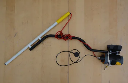
A typical metal detector
The method used to build a metal detector is very diverse and it all depends on the application of metal detectors. This application can be used for detection of metallic as well as non-metallic objects . Usually all applications for metal detectors are not necessarily for metals but may also be used for non-metallic objects (not all nonmetallic objects).
Beat Frequency Oscilator
One type of metal detector is the Beat frequency Oscilator (BFO) type. The method used in metal detectors in general is the change in oscillator characteristics when there is a sensor near the presence of metal.
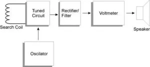
Principle of Metal Detector with Beat Frequency Oscillator
Block Diagram of Metal Detector with Beat Frequency Oscillator
Detector works based on the resonant frequency that has been set to change when there is a metal object that is located close enough to the sensor search coil. The tuning circuit (tune circuit) must be a part of the oscillator circuit so that if the sensor coil is approached by a certain metal then the output frequency of this oscillation circuit will change. This variation of output frequency changes depending on the selected frequency. Higher frequency selection will cause the circuit's sensitivity to increase as the frequency changes are greater. Fixed if the frequency selection is too high then in practice will result in a system that is not sensitive. This is because at high frequencies most will not be reflected back but will be absorbed by the ground, building materials.
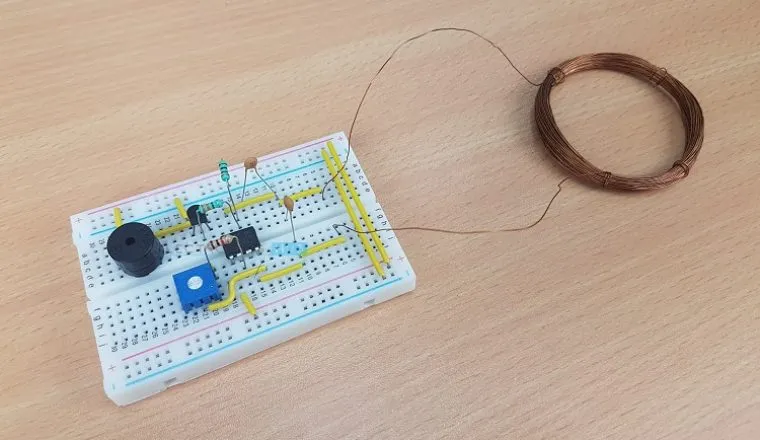
Metal Detector circuit with Beat Frequency Oscilator
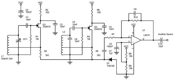
metal detector circuit diagram
Frequency used (f1-generated by tank circuit with L1) usually above capability human hearing. Because it can not be heard by human refreshment then the frequency changes that occur also will not be heard anyway. To overcome this it must be made a distinctive tone (audible frekuency-f2) which indicates a change in frequency. This is what the beat says.
By mixing the second signal (f1 and f2) will produce signals f1, f2, (f1 + f2), and (f1-f2). The signal that can be heard by human hearing is the signal (f1-f2). So when there is a change in frequency caused by changes in the characteristics of the search coil can be heard by humans as the beat-beat is changing. The rhythm is the signal (f1-f2).
Setting VC1 is not easy as this requires experimenting on certain metals. Similarly, the setting of beat rhythm is heard because in a certain condition this beat rhythm will feel very annoying. So it is not impossible not to produce beat or beat rhythm lower than the normal state because all of this can be set on VC1.
So when there is a change in the characteristics of search coil it will also produce a sound frequency depending on the frequency difference generated by L1 and the frequency generated by L2.
This method still has a weakness that is the output frequency variation is still too small so that the frequency change is almost invisible. In addition to a particular condition can produce a frequency under audible sound. For that we need to reconfiguration on the coupling capacitor and the frequency value used.
The values of the existing components in the series of "Metal Detector Circuit with Beat Frequency Oscillator" above are certain values on a metal. So for certain metals then the value of the components need to be adjusted especially VC1, C1, C4, and C5.
Inductor L1 is formed from coil which function as search coil. This inductor will resonate together with VC1 to produce a high Q tank circuit. The second oscillator is formed from L2, C4, C5, R4, and Q2 and this oscillator circuit will produce a signal with a fixed frequency. D1 serves as a simple mixer between f1 and f2 and will generate signals with frequency (f1-f2) and many harmonic signals. The signal with frequency (f1-f2) is made so that it can be in an area which can be heard by human hearing.
Suppose f1 at 100KHz and f2 at 101KHz then after dimixer, signal (f1-f2) will produce signal with frequency 1KHz. This differential signal must be amplified first by using an opamp which can only drive high-impedance headphones. If cool to be used for regular headphones then LM741 can be replaced with amplifier-type audio amplifier chip. Because the output audio output has a low impedance. The gain amplifier setting is determined from settings R7 and R10 and if required then the output of the LM741 can be inserted into a power amplifier circuit to be able to drive a speaker.
The circuit in the picture "Metal Detector circuit with Beat Frequency Oscillator" above is very simple to allow for frequency drift - frequency shift. This is usually caused by a temperature factor. However, this problem is not a serious problem. This problem can be handled by looking for capacitor components that have considerable temperature tolerance. In addition the PCB layout also has a great influence on this problem.
The size of the search coil depends on the sensitivity of the metal detector and the shape of the sensor itself. For example, a large search coil can certainly easily find the metal sought in a large area rather than a metal detector with a small search coil. In contrast large metal detectors can not pinpoint the exact location of cables on a wall due to their large sensor size.
So the bigger the search coil then the accuracy is smaller but the sensitivity is bigger but small search coil instead, usually used for compact metal detector, has high accuracy but less sensitivity. The shape of the search coil is usually a circle or square. In addition there is a need for a shield layer that serves to reduce the effects of electrostatic and the effects caused due to capacitive objects.
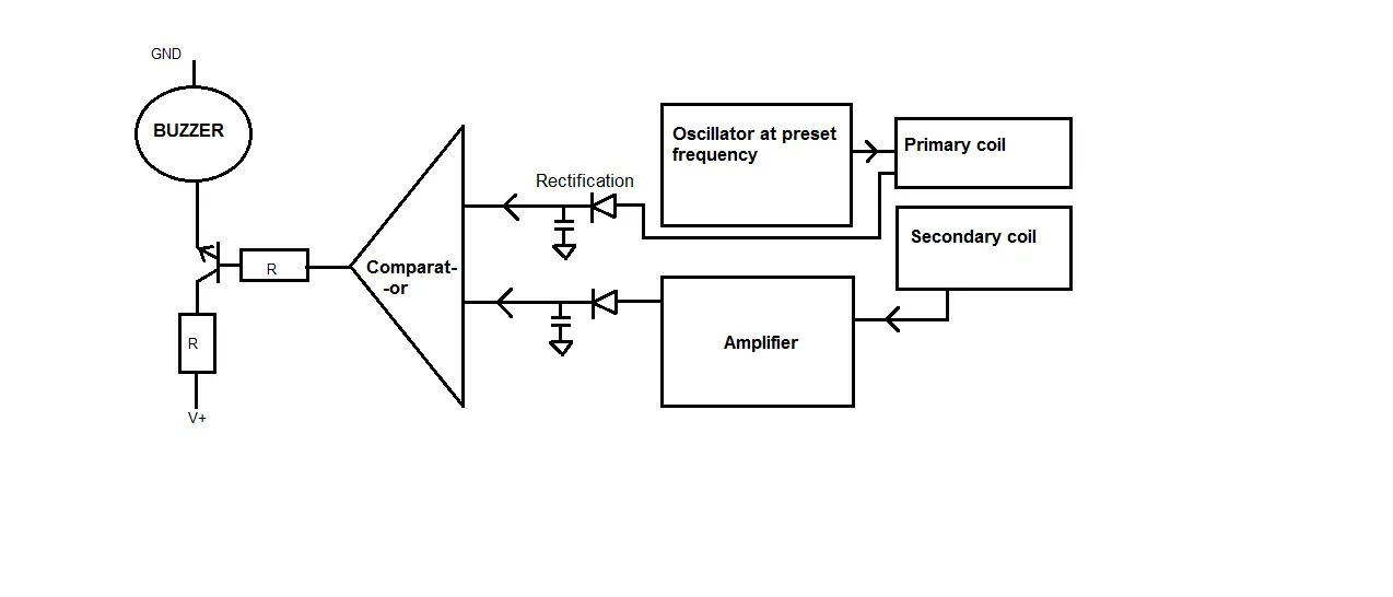
Resonance Detector with Fixed Frequency
In this detector, the principle is almost the same as BFO but slightly different on the tune circuit part. Changes in characteristics of the search coil will cause the Q value to shift so that the signal with fixed frequency amplitude changes. When the search coil is closer to a metal, the Q value will be precisely at the frequency of the signal generated at the fix frequency oscilator and will produce the signal with the maximum peak.
Resonance Detector with Fixed Frequency
So by using this detector will get changes in the amplitude / voltage level of the signal generated by the oscillator. The high-level signal level is generated from the handling and filtering of oscillator signals tuned by L characteristics on the search coil.
Voltmeter Substitution method
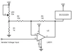
circuit for Voltmeter Substitution method
When the threshold voltage is reached then by connecting a comparator to the output of the rectifier / filter block and LM311 output, a comparator, in a buzzer there will be a sound when it detects the presence of a metal.
R1 and VR1 are used to determine the threshold voltage and R3 is used to adjust the hysteresis in the LM311 comparator process. Hysterical is absolutely necessary to prevent oscillations around the trigger region. Using the circuit in the "Voltmeter Override" image above, the buzzer will not work until the discovery of a metal.
For a detector version that uses a chip only, a series of metal detectors can be built using the CS209A chip. This chip is designed for the purposes of metal detection. This chip is usually used for mini metal detectors. The operation works similar to a resonant detector that uses a fixed frequency. The output of this CS209 chip can then drive a buzzer.
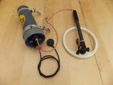
Metal detection and Magnetometers
Another method of metal detector is to use a magnetometer. These detectors are commonly used to detect deep-grown metal in the soil.
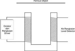
Metal Detector with Magnetometer Method
Metal detectors using magnetometer methods are not immune to disturbances caused by magnetic fields caused by electrical grids, or materials containing magnetic materials. However, this metal detector is most promising for the best results than metal detectors with other methods.
Because the received magnetic signal is so small the construction of the device needs to be taken into consideration as well as the oscillator circuit and its driver.
When there is metal then the signal generated by the oscillator will be stronger, the higher the peak of the signal will produce a higher voltage level as well.
How to determine the presence of a metal with a metal detector also determines the success of the intended metal search. Although in some latter methods everything is determined from the readings of voltmeter is not necessarily because by determining trigger level at a certain level it can be used to sound a buzzer or turn on an LED.
By searching for the maximum conditions it can be concluded that the metal lies in the area. By using a search coil more can be generated the right appointment in a shorter time.
It is important that in reading the results of a detector, the conditions may vary depending on the metal material contained and the depth to the soil surface when tested / detected using a metal detector or metal detector.
References used:
- https://en.wikipedia.org/wiki/Metal_detector
- https://www.electronicshub.org/metal-detector-circuit/
- http://www.3hconsulting.com/techniques/TechMetalDetector.html
- http://www.pcbheaven.com/opendir/index.php?show=271766lz274669if3491bf74
- http://igkelectronics.com/how-do-pulse-induction-metal-detectors-work.php
- https://www.wikihow.com/Build-a-Metal-Detector
- https://medium.com/@ssaurel/learn-to-create-a-magnetometer-metal-detector-on-android-51a73011e4ea
Support @steemstem and the #steemstem
project - curating and supporting quality STEM
related content on Steemit
