Unlike direct current (DC), in alternative current (AC) there are 4 types of powers:
Active power, measured in watts (W)
Reactive power, measured in volt amperes reactive (VAr)
Apparent power, measured in volt amperes (VA)
Deforming power, measured in watts (W)
Energy is equal with the product between power and a unit of time:
Energy = power x time
Active power
Active power, also called “true power” or “real power” is the only one you pay for as a house owner. As signification, the active power is equivalent with the same amount of DC power that would dissipate the same amount of heat on a resistive load. This power can be converted into other types of power such as mechanical, light, heat, sound etc.
The formula to calculate active power is:
P=U ⋅I ⋅cos(φ)
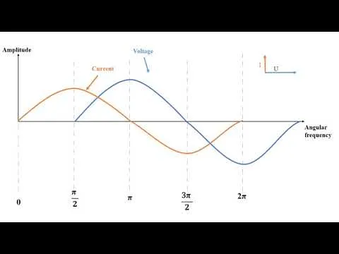
where, φ is the phase angle between voltage (U) and current (I)
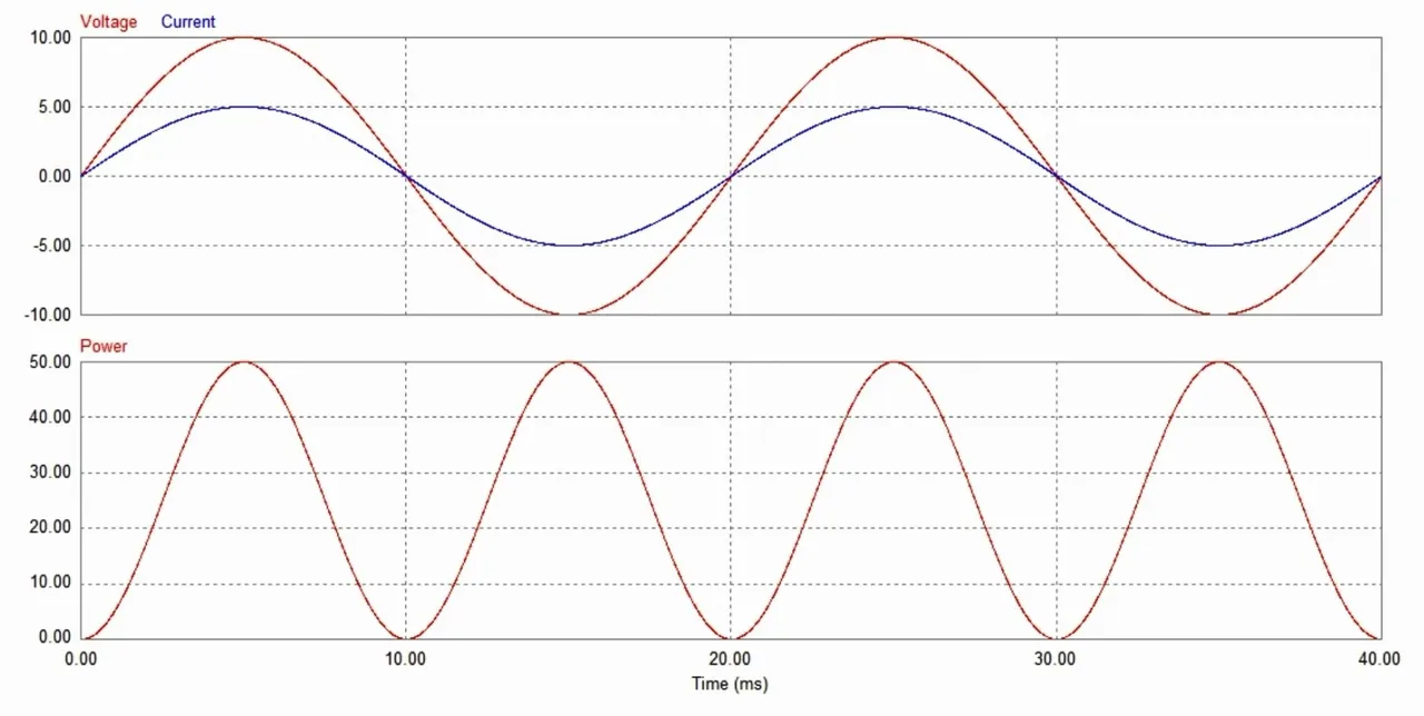
On a pure resistive load, the phase angle is 0, so, cos(φ)=1
The formula becomes:
P=U ⋅I ⋅1 => P= U ⋅I
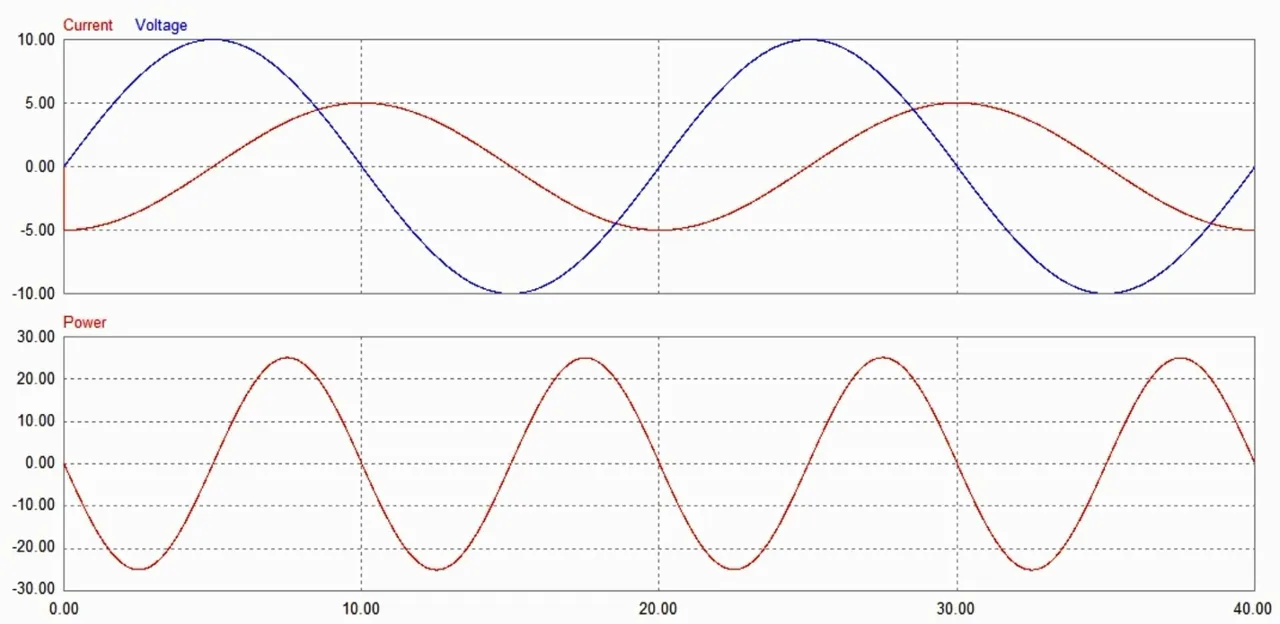
Reactive power
Reactive power on the other hand it’s a complex (or imaginary) power and can not be converted into anything else. It appears when non linear loads like coils and capacitors are connected on the power grid. Its main utility is to magnetize the magnetic core of inductive loads such as induction motors, transformers and so on.
The formula to calculate reactive power is:
Q=U ⋅I ⋅sin(φ)
On a pure resistive load sin(φ)=0, so there is no reactive power flowing.
On a pure inductive or capacitive load however, the phase angle between voltage and current φ=90, so sin(φ)=1. Therefore only reactive power does flow in this kind of circuit.
Inductive power factor:
Capacitive power factor: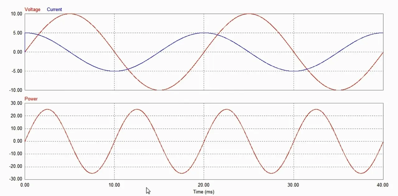
In a RLC circuit, where is also a resistive component, sin(φ) is less than one, therefore both active and reactive power is flowing through this kind circuit.
Notice that the reactive power flowing through an inductive circuit oppose the reactive power flowing through a capacitive circuit. As a rule of thumb, inductive loads like coils and motors consumes reactive energy from the grid, while capacitors generates reactive energy.
House owners do not get charged for the consumption of reactive energy. Big companies instead, do get charged, as their reactive power consumption negatively affects the overall power factor.
The flow of reactive power overloads the power grid with additional current flow. Therefore power and distribution electrical company must oversize their electrical generators and upgrade their infrastructure, in order to work with apparent power, instead of active power.
Apparent power
Apparent power is the complex sum of active and reactive power.
S=P+jQ
where:
S – apparent power
P – active power
Q – reactive power
The formula to calculate apparent power is:
S=U⋅I
On a phasor diagram, the 3 powers can be geometrically represented as a triangle of powers. Reactive power is 90 degrees phase shifted from active power. Apparent power unites those two vectors and forms a hypotenuse which can be solved using the Pythagorean Theorem:
S2=P2+Q2
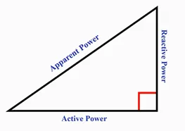
The power factor is the ratio between active power and apparent power and always belongs to the interval between 0 and 1:
cos(φ)=P/S
Deforming power
Deforming power, although it does not have the same popularity as the other 3, it plays an important role that affects all consumers. An ideal power grid would have a voltage waveform of 50 hertz for Europe and 60 hertz in USA. But in reality all non linear loads induces current harmonics in the power grid, which translates into voltage harmonics which are passed through the entire grid. Harmonics are high frequency ripples which distorts the waveform from a perfect sinusoid.
An example of waveform which contains a 50 hertz fundamental frequency, upon which is added the third harmonic (150 hertz) and the fifth harmonic (250 hertz) can be visualized on the following graph:
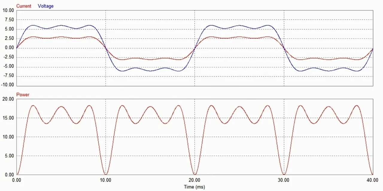
The harmonics of voltage and current creates deforming power which is passed on the power grid. The presence of deforming power lowers the efficiency of non linear loads.
For example an induction motor is driven at a fixed speed from a 50 hertz power grid. The presence of the low amplitude third harmonic will try to drive the motor with 3 times more speed, the presence of the fifth harmonic will try to drive the motor with 5 times more speed and so on. Meanwhile only active power is converted into mechanical work, deforming power is converted into heat, which lowers the efficiency of the motor.
The only way to avoid the absorption of deforming power is to use a low pass filter, which attenuates the high frequency harmonics.
Watch the following youtube video for the complete in depth explanation of AC powers.
....................................................
All the materials used in the production of this post belongs to me.
If you like this kind of content, please subscribe to the youtube channel above, this motivates me to invest more time and effort in the production of future videos and educational posts like this one. And trust me, I have a tone of great ideas on the way.
Thank you for reading and have a nice day!