Keep an eye on your CPU temperature by means of GPIO controlled LEDs, Python and the GPIO Zero Library. This is handy if you’re overclocked and will very quickly alert you to any problem with your cooling system, especially if you access your Pi via SSH and VNC exclusively (like I do) or run in headless mode.
Cooling:

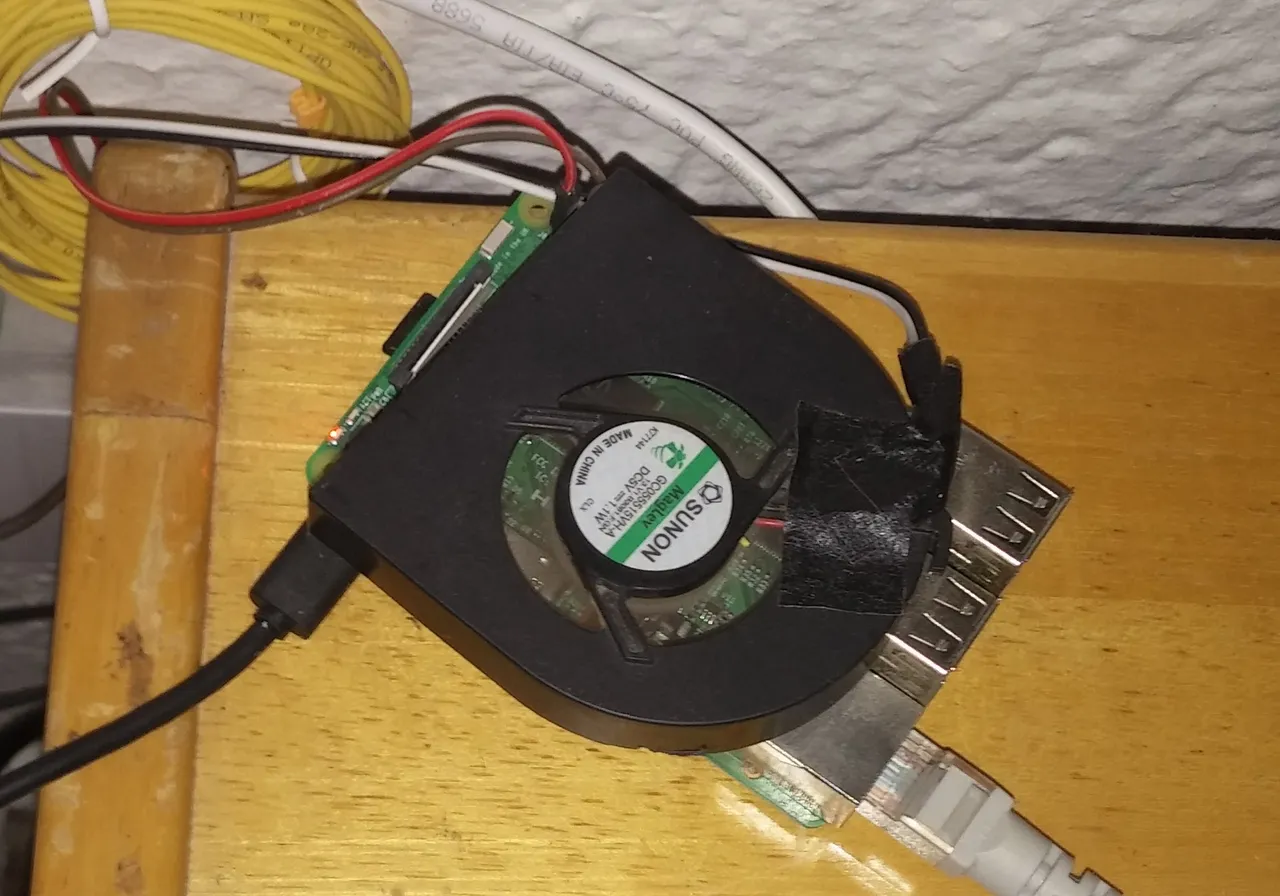
Really simple and free/cheap. Any laptop fan will do and performs perfectly. A water-cooled system may look pimped out and all, but remember that the power and fun of single board computers lie in tinkering. When your cooling system is 10 times bigger than your board and making it vulnerable to leaks when you need to tinker, you are basically shackling this amazing little device and the opportunity to learn new skills.
You will probably often change SD cards or need to access the pins. If you use your Pi as an affordable dedicated Kodi box or for your kids to play and learn with, there is no need for cooling and so justifies putting it in an aesthetically pleasing and protective enclosure. For all other applications, it should be lying loose and unencumbered. Free the board!
You don’t have to run it at 5v. 3.3v is more than adequate and completely quiet. You can switch to 5v during stress testing, but it’s pretty noisy, even some of the newer ones. Mine came from stripping two old Win XP-era laptops.
Simply attach the female sides of two jumper leads to the black and the red wires connected to the fan. Most fans will have a third, often yellow, control wire. You can cut this off completely or tape it to the side of the fan.
Connect the red wire to one of the 3.3v pins and the black to one of the ground pins. If the fan doesn’t kick in, try the 5v pin.
I get the the same results whether I use a vertical or horizontal fan.
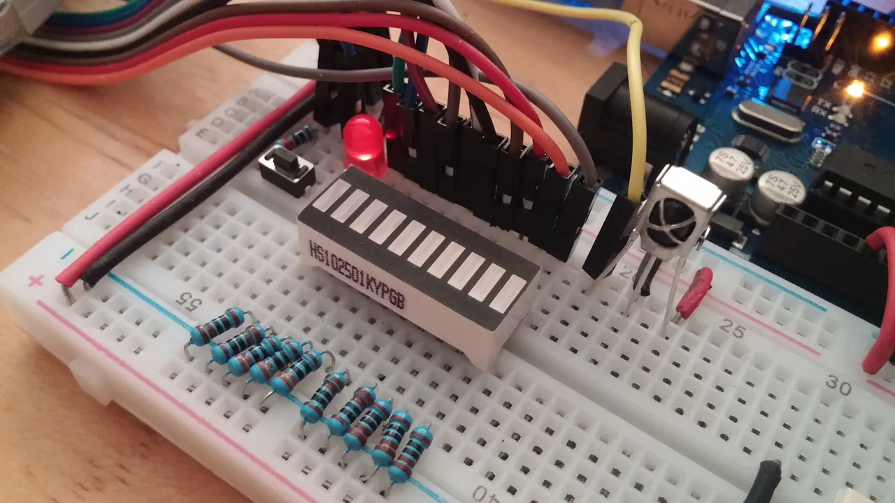
Bar Graph LED Temperature Indicator
This can of course be done with any row of LEDs. Some bar graphs are single colour and you can play around with resistors of similar value to get these to your desired brightness. The bar in the video is multi-coloured and some colours are way brighter than others. I started with 330Ω on all LEDs, but found the blues and the greens blindingly bright compared to orange and red, so I replaced them with 1KΩ which smoothed things out.
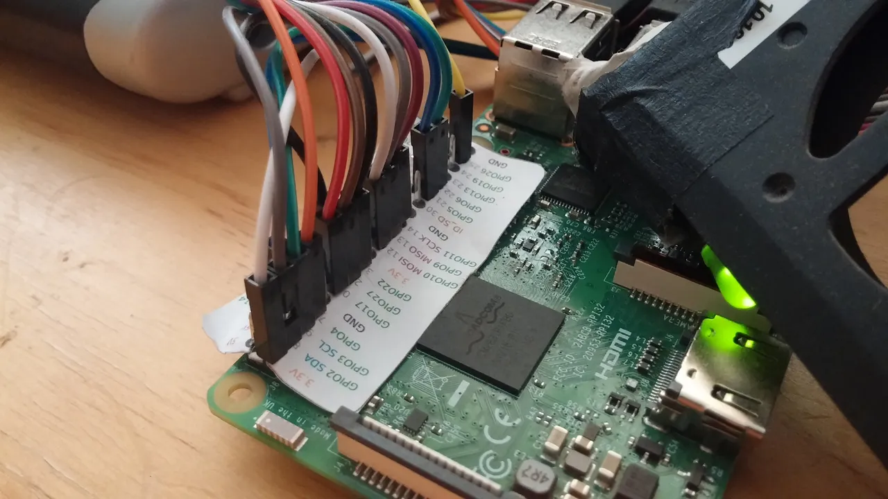
As opposed to Arduino, GPIO pins are not numbered and named on the Raspberry Pi board. It is difficult to count them by eye to get to the right one. A single inkjet printed reference takes that headache away. Print this at 100% scale, line up with your pins and from one side, start pushing the pins through the paper. As many will fit on an A4, print a few, should it go askew or tear.
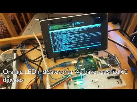
Demo
Using Juice SSH, I am monitoring the system on a first generation Nexus 7 through htop while I put load on the cores in desktop mode via VNC on my laptop.
Code (Python, Run from IDLE 3 or Equivalent):
from gpiozero import LEDBarGraph, CPUTemperature
cpu = CPUTemperature(min_temp=40, max_temp=70)
leds = LEDBarGraph(2, 4, 17, 27, 22, 10, 9, 11, 5, 6, )
leds.source = cpu.values
You can set the temperature range to your own requirements (Celcius)
The same goes for the LEDBarGraph values – mine represent the available pins physically closest to each other because I’m using a ribbon of wires.
This code will of course also work if you are using discrete LEDs. The bar graph is merely a strip of 10 single diodes cast in resin. It does not contain an IC and the LEDs are not connected to each other in any way.