In this article, I would like to describe some fundamental principles when designing an object that should later print on a 3d printer. I'll focus on FDM printer and their challenges as these are the most commonly used ones. But keep in mind, some issues are different for powder and resin 3d printers.
As you will see I use Autodesk Fusion 360 as preferred design software. It was really easy to learn and get used to it.
To illustrate the concepts I will take my latest design for the Esso 250 can contest from myminifactory.com as the examples. More details about the CanBot can also be found in my earlier post "CanBot - Sculptures from 250 cans" here on Steem.
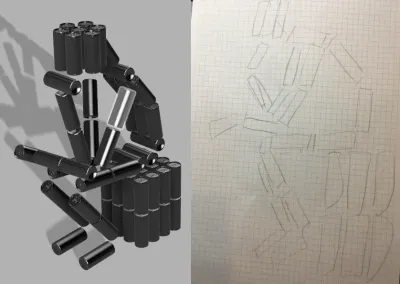
The task for this contest was to design something for upcycling a 250ml slim can. I had nothing else in my mind as inspiring a new “Can”-art genre! ;-) I wanted to print a different kind of connector so you can build sculptures of any kind with the 250ml cans like it would be a Lego brick. My starting point was a draft with pen and paper and later the same model in Autodesk Fusion 360 just with the cans itself.
And here the final result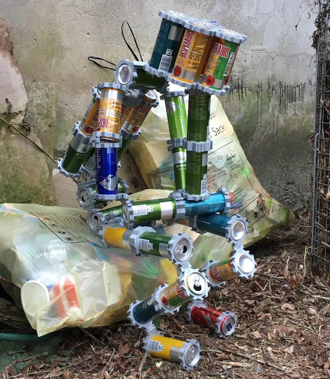
I took this little elaborate sculpture to cover as many complex connection types as possible and came up with the following design principles.
Less is more
I knew it would be a multi-part design, but I did not want to overdo it and find connectors that fit many different requirements.
Easy to print
Optimized for FDM printer. If somehow possible I also wanted to avoid supports, difficult overhang areas, and bridges
Avoid post-processing
No problematic post-processing of the printed parts. In the ideal case, no sanding and no glue. Everything should fit well together.
To accomplish these we are looking into following things that you need to consider:
- Tolerances in Multi-Part Designs
- Avoiding overhangs and supports
- Using filets to prevent tough spots.
- Improving printability with chamfers
Tolerances in Multi-Part Designs
When I have multiple parts design, I start with four different tolerances in the parameter sections of my fusion design.
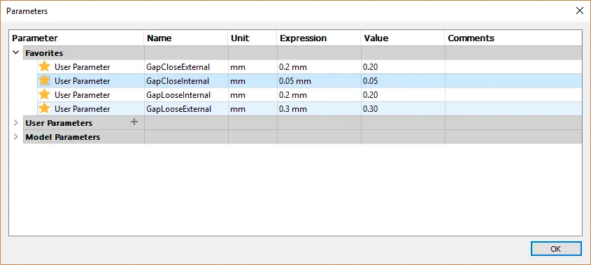
The close gap is for parts that should fit together but don't move.
In the ideal case, you need a decent force or use pliers to put them together, but they will not lose themselves.
The loose gap is for parts where movement between the components is required. E.g. hinges or other things.
The internal vs. external gaps I use to differentiate between components like the 250 ml can that are not printed and parts that are printed. All conventional materials for FDM printer shrink when they cool down a very few percentages. Therefore, the gap between two printed elements is different than between a printed and a non printed part that didn't shrink.
These gaps are also different depending on the material you are printing with. Having them as variables allows me to always change the printing material and adjust the designs automatically when it is required.
To apply the gap values I typically use the offset function in sketches from Fusion 360.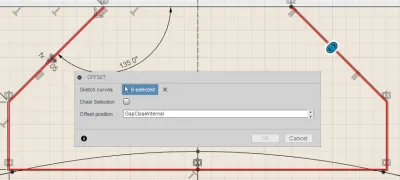
When you already have the 3d object you can also just push a face.
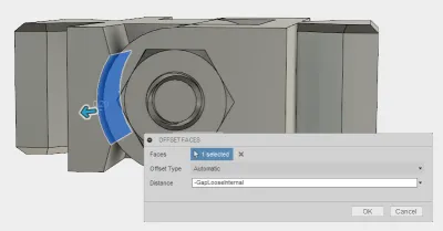
Remember to use the parameters that we defined before when you define the distance for the offsets.
Avoiding Overhangs and Supports
As standard FDM printers build the object from bottom to the top, layer by layer, there is always the law of gravity that prevents us to print features that don’t have some matter below. To prevent this you have to use supports that are automatically calculated by any good slicer or change your design and avoid those issues.
Support structures are not bad in principle but you will need to remove them in a post-processing step. And often when a support is on a visible surface you have to sand the surface where the support was. Although avoiding support is not always possible you can optimize to avoid support with different options:
Split objects for printing
If you don't want to change the appearance you should think about splitting the object and printing it in 2 pieces that would avoid supports. This is really useful when you want to avoid supports on visible surfaces. Even if a support can't be avoided completely you can still try to split and slice the parts in a way that they are not on the surface of the final part.
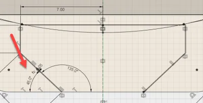
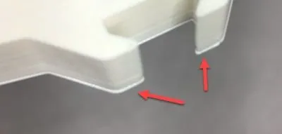
Carefully choose the angle for overhangs
When you have overhang areas you might consider making the angle only between 45-50 degree instead of 60+. My printer can print until an angle of 60 but quality suffers. I would recommend staying below 50 degrees until you might need support when these surfaces are visible in the final object.
Here I chose a 45-degree angle mainly to be flexible with printing the joint in all orientations.
If you carefully place your supports and overhangs and also have a low layer high you will not need to sand your part afterward.
Using fillets to prevent tough spots
Another challenge when printing with FDM 3D printers is thin details. If you have such corners or thin walls the printer might reduce precision or the stability of those parts is not very high. A common problem of small thin walls is also that they have difficulty to stick to the printed as they are cooling down they tend to warp.
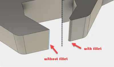
In my example, I used fillets on sharp edges and in the area where the different parts should fit together. In this design already very thin fillets where enough to make sure the corners stick to the bed and are precisely enough printed to fit with the connectors.
Improving printability with Chamfers
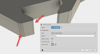
Similar to fillets, a chamfer is used to smooth edges and corners. But I use these for different purposes. When you have a multi-part design and you want to avoid sanding you sometimes have the challenge that the first layer doesn't have been tuned correctly compared to the rest of the part.
In typical cases, the result is 2 parts not fitting together without sanding away this material. To increase the tolerance for this I do add small chamfers in the areas where this details matter.
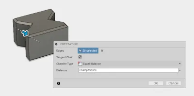
In this example, i used chamfer for the connector on all edges that are possible print side.
This will avoid sanding in many of the cases where the printer is not 100% calibrated.
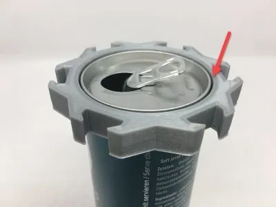
I also use chamfers or fillets when there are areas that should fit together with external parts. Here adding more tolerance on top of the gaps is often useful to have the part ready without any post-processing.
That's it for me right now. I really hope you found some of those tips useful!
Have more to add? I would love to see your tips in the comments as I'm always eager to learn more!