the Hybrid Electric propulsion system for an aircraft is a system that combines the advantage of fuel-based systems and battery powered systems.
In combining conventional combustion engines with electric engines and batteries lie some great opportunities for the future of aviation. First of all, batteries do not emit any exhaust gases when converting its energy to power.Furthermore, the noise and vibrations from electric engines are virtually zero, reducing the noise pollution, increasing the cabin comfort, reducing the maintenance cost of the engines, and increasing the safety.
Unfortunately, hybrid-electric propulsion systems come with several downsides that form a potential risk for its success. The foremost downside is that the gravimeter energy density of batteries is in the order of 60 to 100 times lower compared to conventional fuel, leading to more required weight for energy storage. However all hope is not lost because this work employs the use of structural batteries technology which will help in the reduction of weight penalty;the fuselage of the aircraft is proposed to be multi-functional and this does not negate the structural capacity of the fuselage.
The advantage of this method is the reduction of overall mass, and increase in range/time of flight for the same energy capacity and power ratings of the battery.
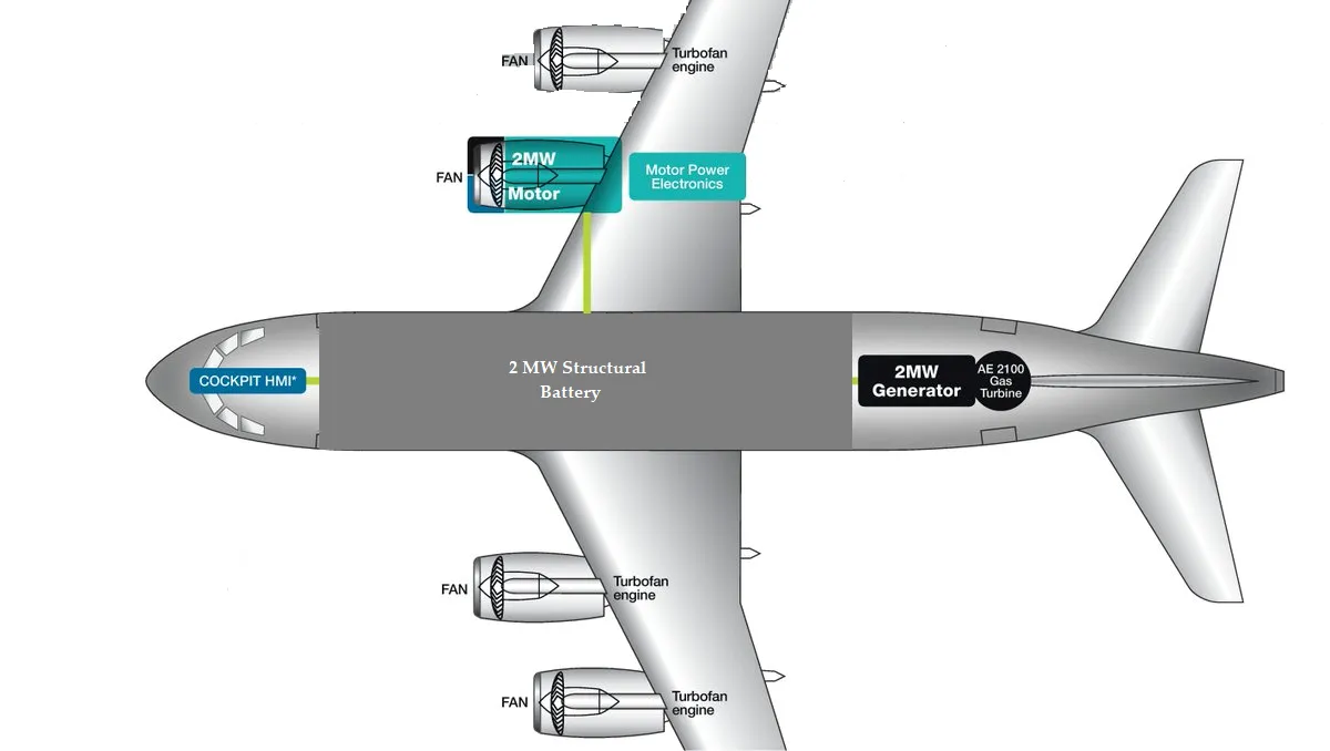 Diagram of the Proposed structural HEPS
This work implements a conventional (ICE) and an Electric system with the aid of structural battery to reduce weight penalty; using airbus e-fan and alpha electro, in the testing and analysis of various scenarios.
These analysis includes, the state of charge and voltage levels; the current levels of the motor, load and generator in the case of the hybrid-electric system; shows the range and maximum flight time; and finally the relationship between the payload and the range; and the payload and the maximum flight time for both hybrid and fully-electric Airbus E-Fan aircraft.
The battery is modeled in a series resistor and a charge-dependent voltage source. The voltage is a function of charge as expressed in equation (3.1). This equation ensures that the voltage is zero when the charge level (SOC) is zero. Hence, the increasing rate of voltage drop with decreasing charge levels is replicated.
𝑽=𝑽𝟎(𝑺𝑶𝑪/𝟏−𝜷(𝟏−𝑺𝑶𝑪))
where:
0 is the voltage when the battery is fully charged at no load – the nominal voltage
(state-of-charge) is the ratio of current charge to rated battery capacity.
is a constant that depends on the ampere-hour rating.
If the SOC is less than or equal to the lower limit charge, the propulsion is powered by the turbine engine irrespective of the flight profile or time. The engine torque (𝜏) for actual power delivered (P) from the engine for a given engine speed (Ω) is as expressed in equation.
MATLAB Model
The proposed methodology is implemented in Simulink package of MATLAB (2018a). An HEPS has a combination of internal combustion engine (ICE) and electric system.
Internal Combustion Engine (ICE)
As shown in figure 3.1, one of the four ICEs (turbofan engines) was converted to an electric motor. In this project, a spark-ignition general ICE was used. shows the ICE model.
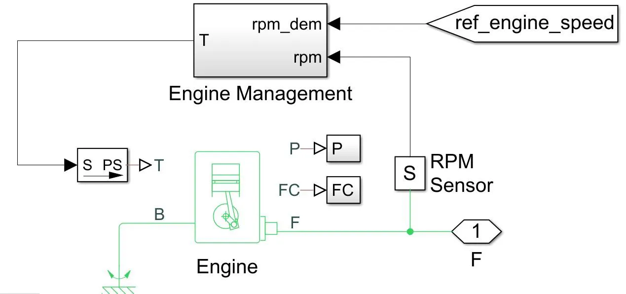 Spark-ignited internal combustion engine (ICE)
The throttle level of the ICE is managed by the engine management system through a reference speed. The outputs of the engine include the instantaneous power (P), fuel consumption rate (FC) and the rotational force (F) from the engine crankshaft.
Generator
A brushless motor with closed-loop torque control is used. The rotational force (F) from the engine crankshaft of the ICE is connected to the mechanical rotational port of the generator ! Reference source not found.. As a generator, the mechanical power is converted to electrical power. The positive and negative terminals of the generator are connected to two DC-DC converters – high-voltage direct current (HVDC) and low-voltage direct current (LVDC).
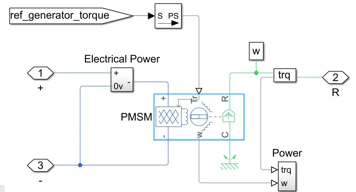 HEPS generator implemented with a servomotor
DC-DC Converters
This power converter regulates voltage on the load side. The required amount of power is drawn from the generator in order to balance the input power, output power and losses. The HVDC powers the aircraft propulsion, while the LVDC powers the lighting, heating, avionics and fuel pump.
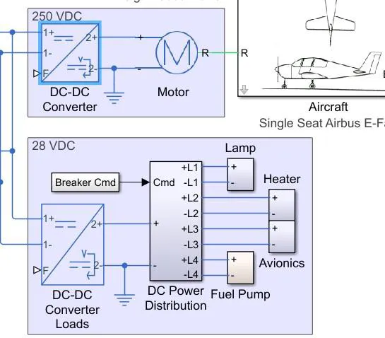
Furthermore The motor that drives the aircraft is also a brushless DC motor that takes the electrical energy from the HVDC and converts it to mechanical torque that propels the aircraft. A battery pack is connected to the HVDC. As proposed in this project, the battery pack is integrated into the HEPS fuselage to form a structural battery pack. The power from the battery pack is used during cruise and landing if the energy in the battery pack is not depleted. However, the ICE supplies the power to the HVDC during take-off and climbing.
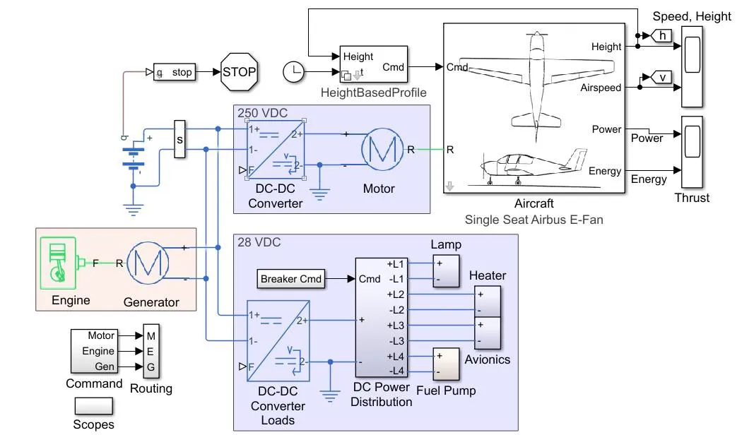
Implementation of HEPS in Simulink/MATLAB environment
In subsequent post we shall be looking in to the flight profile of the aircrafts on which the methodology was tested. these Aircraft are #Airbus e-fan and Alpha electro.