Today I'll be showing you what's inside a cheap solar-powered USB power bank, used for charging cell phones or anything else with a USB charging port.
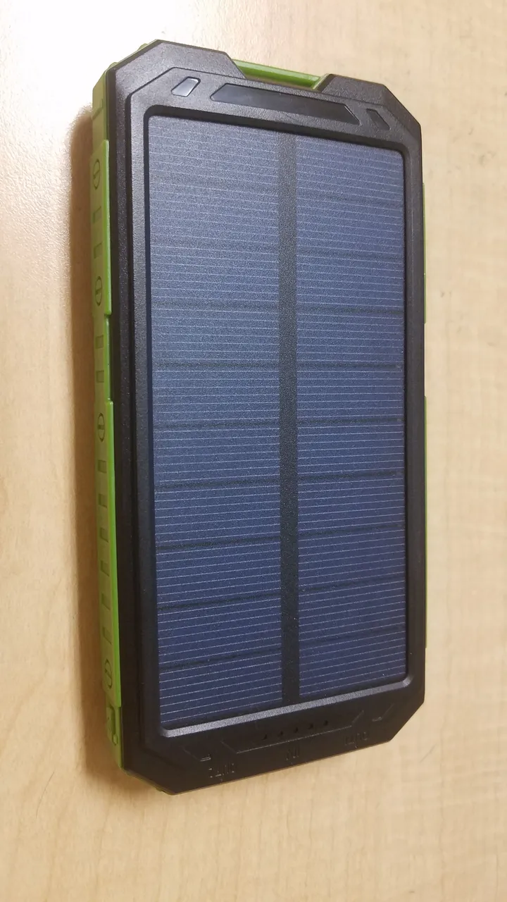
The device is supposed to work by charging an internal lithium battery with power from the sun, collected by a large rectangular blue solar panel fixed to the front of the device. Two USB ports allow for charging two devices at once, and a microUSB port is located at the front to charge the battery in the event that you don't have enough solar power to keep it topped up.
Outside the device
In general, the device appears to work as advertised ... mostly. The two USB ports do indeed power USB devices like charging cables, and the device does appear to charge when plugged in to a microUSB source. It also contains a row of four bright blue LEDs that indicate how charged the internal battery is.
I purchased this device for a little over $10 on Ebay late last year. This will be my second time taking it apart due to a rather dubious claim made by the seller: That is, the seller claimed in the item description and title that this power bank had over 30,000 mAhr of capacity.
30Ahr of capacity corresponds to almost 100 Watt-hours of battery contained in this tiny little rectangular box. If my understanding of modern battery technology is sound, this isn't physically possible in such a small container. If true, this small power bank could charge most modern cell phones ten times before needing a recharge. Unfortunately Chinese/Malaysian Ebay sellers like to massively inflate statistics that they know few will actually check, resulting in the lowest price tab for power banks being filled with ridiculously high battery capacities (same old garbage as with cheap stun guns and their hundred million volt false ratings...). That being said, even if this battery pack has just a fraction of 30 Ahr it will be useful to me, hence why I picked it up in the first place. Thankfully, a teardown with reveal just how badly the seller was lying.
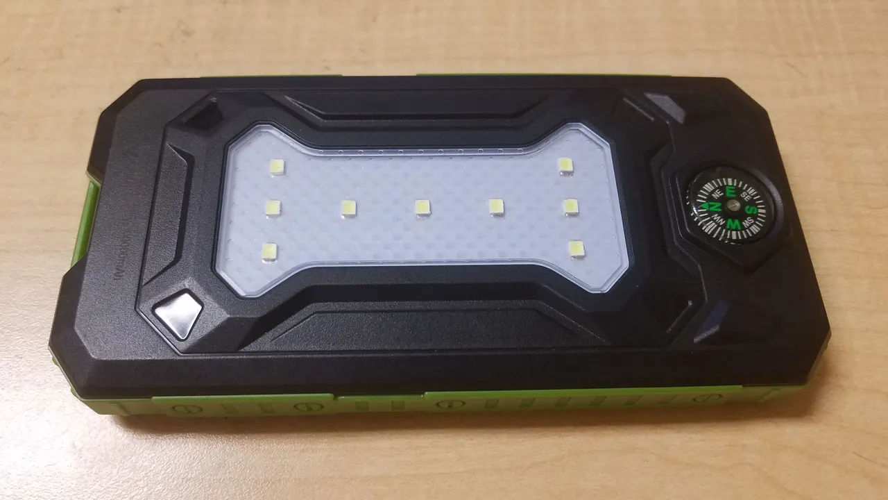
The device is actually somewhat well built, with cheap but sturdy plastic surrounding the exterior. An array of somewhat bright LEDs serve as a flashlight and a small cheap compass is strapped to the front panel of the device. If you shine a flashlight on the solar panel, a green LED lights up, indicating that the circuit is indeed detecting light somehow.
Now to break into this thing.
Teardown
The device has no external screws, which is unfortunate. Thankfully, it turned out to not be glued together. The outer shell consisted of two plastic halves, held down by small plastic tabs. A small flat-head screwdriver made short work of this cover and the battery pack opened up with almost no damage to the case - a big plus in my book.
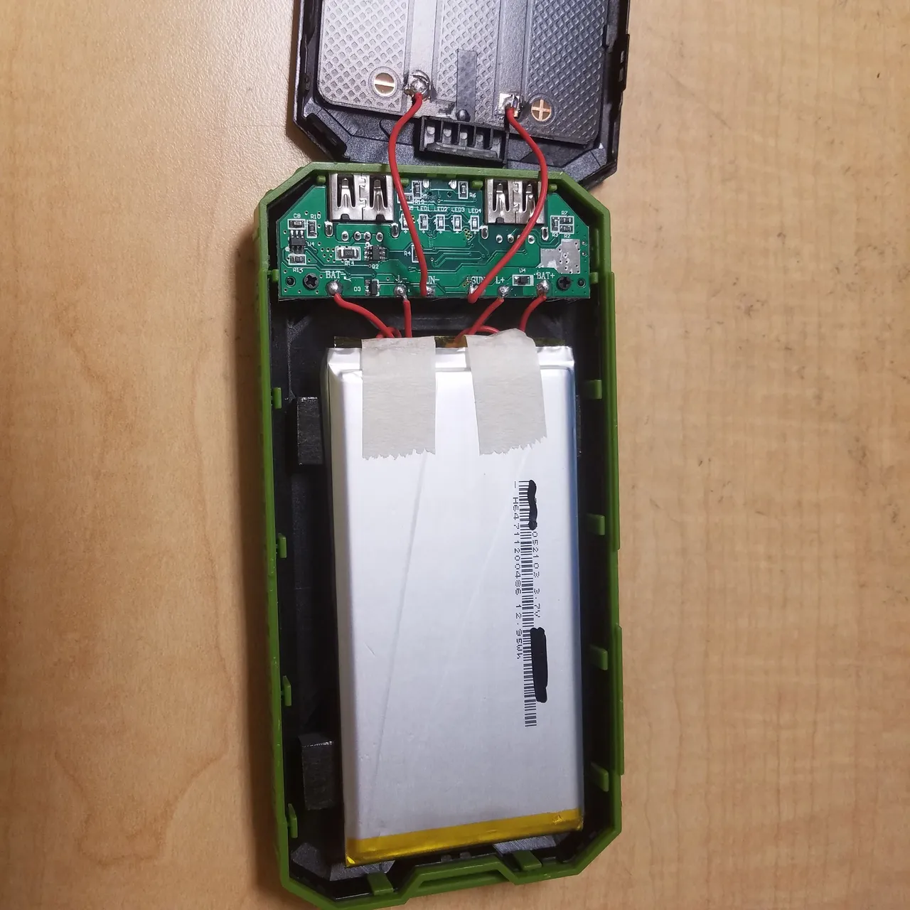
Inside, the solar panel, circuitry, and battery are in clear view. The green PCB contains the USB ports (in and out), charging circuitry (lithium batteries require special circuitry to assist in charging), and a boost converter that boosts the incoming 3.7 volts from the lithium-polymer battery to 5 volts for the USB output ports to use.
Solar Panel
The solar panel is attached to the top cover of the plastic shell, and is in fact not fake. I don't want to take it off and directly measure the power because soldering on my ridiculously messy desk is not something I want to do right now, but based on other panels I've seen I estimate that it produces around half a watt of power under direct sunlight here at 30 degrees latitude.
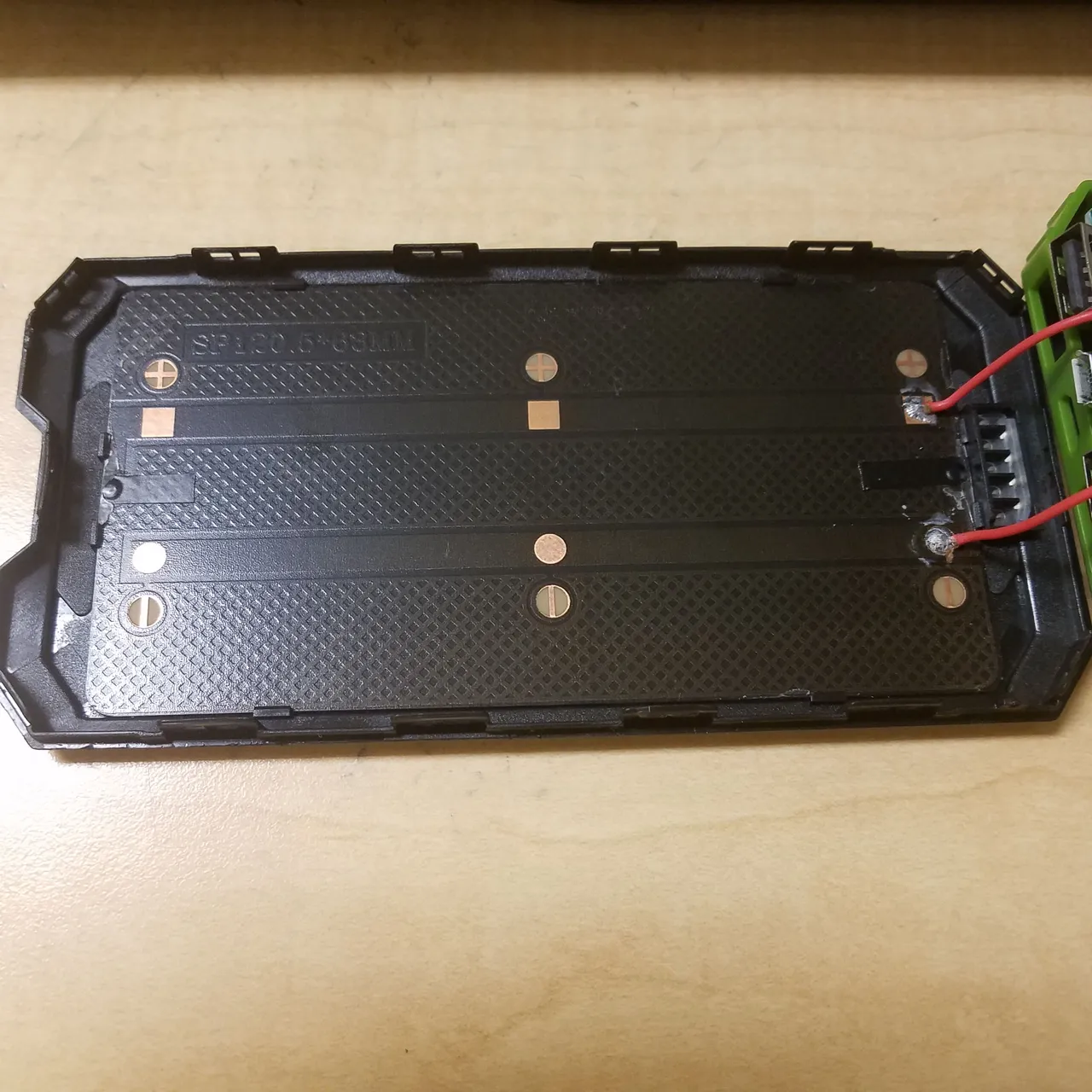
View of the backside of the solar panel. Metal contact points are visible, which can be probed to view the panel's voltage.
Lithium-Polymer Battery
The battery is a real piece of work. This device is a large lithium-polymer battery, and as such is quite light for its energy storage (although this one is big enough to not really be that light). Puncturing this could cause a fire, so I was careful when opening the outer casing of the overall device to not slip and hit the battery with my screwdriver.
Almost all lipo batteries will list their energy storage values on the front of the cell. This one is labelled as a 3.7 Volt cell, which is typical for lithium-polymers. Hilariously, the amp-hour reading (which lets you calculate the overall energy storage of the battery using the voltage) is marked out with permanent marker! Seems false-advertisement seller was actually slightly concerned that someone would open their battery and find out that they had been fooled. Even more hilariously however, not only is it really easy to read the Amp-hour rating by tilting the battery (it's 3500 mAhr = 3.5 Ahr, just over 10% of the advertised capacity!), but the silly manufacturer declined to cross out the overall energy storage value of 12.95 Watt-hours labelled just below the mAhr capacity. I suppose most people just think in mAhr's in terms of cell phone chargers, but the watt-hour value literally lets you back calculate the milliamp-hour value. Anyway, I thought this was quite funny.
Circuit Board
The battery charging circuitry actually seems to be somewhat decent. A button lets you toggle power to the LED flashlight array (hidden underneath the battery - I didn't want to rip off the battery to get to the flashlight LEDs since they are just going to be LEDs and resistors, and doing so would make it difficult to properly re-assemble the battery bank) or view the charge indicators.
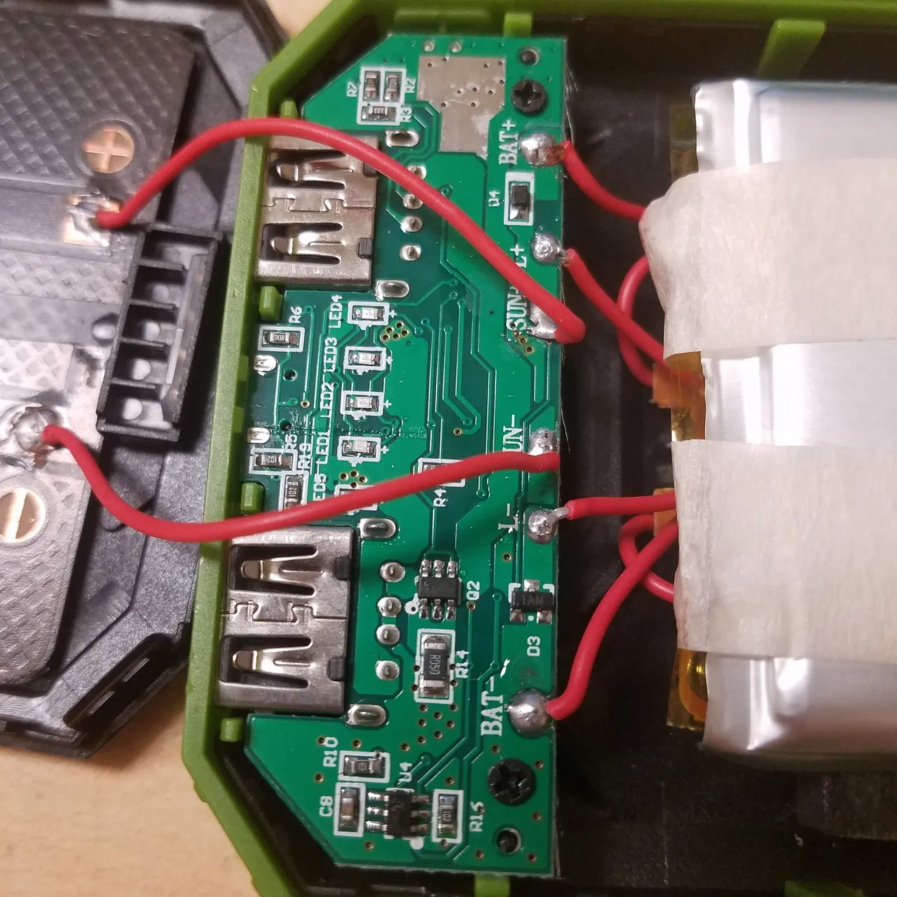
The six wires exiting the PCB lead to the LED array, the battery, and the charging panel.
On the top side, the two USB output ports are visible, along with a few surface-mount transistors. You will also notice the array of blue surface-mount LEDs, which display how high the battery voltage is (how charged the battery is).
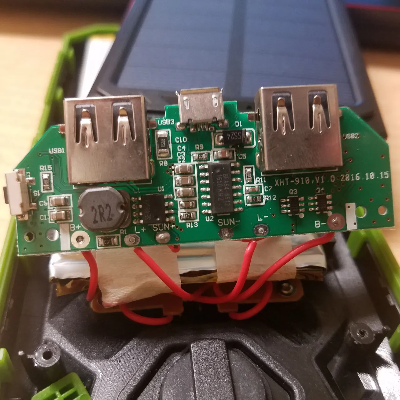
Removing two easily removed screws lets the PCB flip over and reveal the more interesting side. Here we can see all three USB ports (2 USB, 1 microUSB) along with several larger components (unfortunately this circuit is a bit too complicated for me to make a schematic) The large component labeled 2R2 is a small ferrite-core inductor (essentially a coil of wire, or an electromagnetic, with a core containing iron). This device is almost certainly used as part of a boost-converter that takes in the battery voltage (3.7 volts) and boosts it to 5 volts (which the USB ports need to run USB devices). Your phone charges with 5 Volts input, so it is necessary for the power bank to raise the battery voltage before outputting it to your phone.
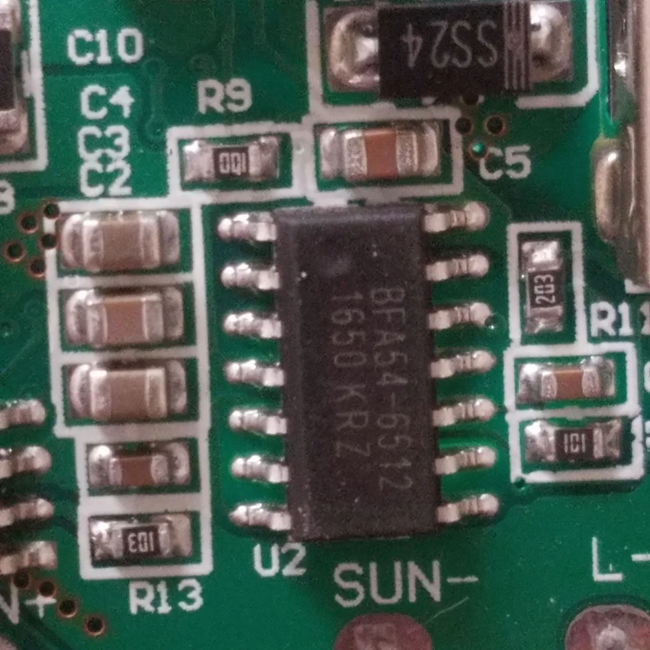
A timestamp on the board indicates it was manufactured about a year before I purchased it. I was unfortunately unable to find a datasheet for the large black IC in the center of the PCB, although it may be an array of MOSFETs (a type of transistor).
Closer examination of other ICs on the board reveal more MOSFET arrays. Here is a close-up image of one of these, located next to the inductor coil.
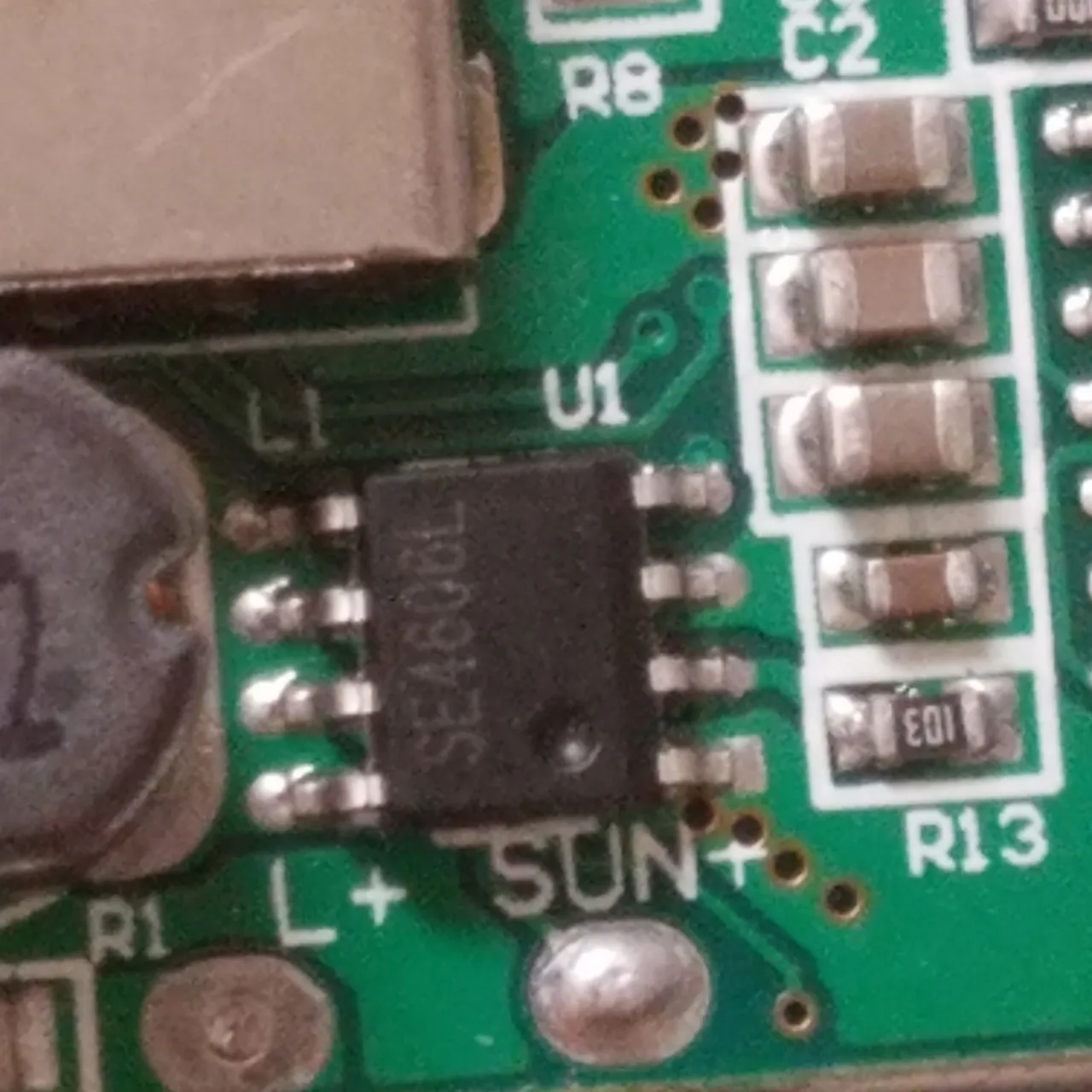
SE4606L MOSFET on the board
What's going on?
While the actual operation of the circuit is quite complicated, the high-level functions are pretty simple.
Photons from the sun strike the solar panel, exciting electrons and producing a somewhat constant voltage/current source. This current is fed via connecting wires into the charging board. The voltage is regulated by the onboard circuitry and passed into the lithium-polymer battery to charge it.
If sunlight is not available, power can be supplied via a computer or wall outlet through the microUSB port. In this case, the voltage must also be regulated to prevent damage to the battery, and the charging current will be higher than for the weaker solar panel. The benefit of the solar panel is that it works anywhere with reliable sunlight.
When you plug your phone into the power bank, the battery provides a nominal 3.7 volts to the protection circuitry. Using the inductor specified previously, this input is boosted up to a higher voltage (and lower current, to conserve energy) of 5 volts. Then, 5 volts DC can be routed to the USB ports and power your phone.
Despite not living up to its obviously fake advertised battery capacity, this device is still very useful for its low price. 13 Watt-hours is not a bad capacity, and I could see this device being useful if you were to be backpacking in the wilderness without any power, or if you were stranded somewhere. Say you get lost hiking - this device can keep your phone or flashlight charged so that you can find your way out and back to safety. The solar panel isn't even really a downside in terms of size, so the device can be used as you would normally use any other power bank.
Being relatively easy to open, I could also see repairs on this device being somewhat easy. No schematic is available of course (it's cheap Chinese electronics so I'm obviously not surprised), and surface-mount stuff is stuff to fix, but any failure of the solar cell, flashlight, or battery could be easily repaired. You could even replace the integrated battery with a bigger one without too much trouble.
Let me know if you have any questions or comments. I apologize for the lack of schematic for this teardown - it simply would have been too much work to reverse-engineer a circuit of this density. To facilitate discussion I'll try to upvote all non-spam/non-fluff, substantial comments.
Thanks for reading!
All images used in this post are my own. You are welcome to use them with credit.