The process & creation of the diy microscope climate chamber
In order to get better and more consistent results for the project Imaginarium of tears, it’s important to standardise the evaporation and crystallisation process of tear fluids. To do this, I would need to create a climate chamber around the microscope. That later on will be controlled by the climate unit controlling the temperature and humidity within that climate chamber at preset values.
With the experiments done for the Tear Collection Kit, data tells me that the optimal temperature and humidity of such a climate chamber would be around 12° Celsius and 40% humidity.
Example of the tear evaporation and crystallisation process.
To do this I would need to upgrade the microscope by building my own DIY climate chamber and a climate control unit.

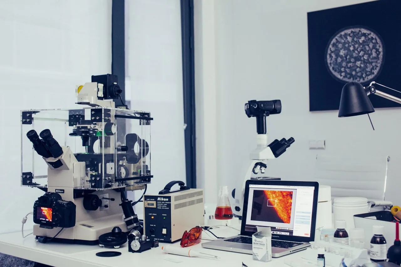
**Current Microscope Setup with the DIY scanning stage. **
Knowing that the microscope had an optional incubator mentioned in its original manual, I went on the internet to see if I could buy the old incubator. Unfortunately as I expected, finding only the casing and or the control box was not easy. Setups where only sold together with the microscope, making it too expensive to justify. Other options like a 3rd party manufacturer where not supporting this microscope or where also just to dam expensive.
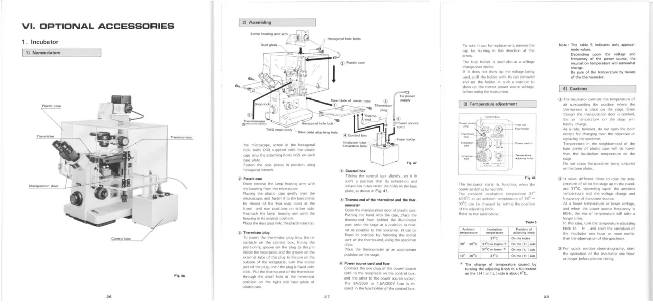
The original optional Incubator mentioned in the original manual as available accessory.
The Climate Chamber:
With the information available form the manual and images from the internet, I decided to design the Climate Chamber myself. Below you can see the preview of the climate chamber, designed by measuring the specific parts of the microscope insuring a snug fit. Tho I did make some adjustments when it came to the “original incubator” design.

Click link to open the fusion 360 file and review the Climate Chamber model: http://a360.co/2F5LfVD
Things that where adjusted:
- Brackets to connect to the microscope.
- Smaller casing, shorter on the left and right side.
- Placement and type of manipulator doors, no hinges but sliding doors.
- In and outtake exhaust to later connect the climate control unit.
- Use of “connectors” in the corners. No glue needed, everything is build modulair with nuts and bolts. This is an important design change, due to traveling everything needs to be easily disassembled into a flatpack.
The idea is to 3D print all of the black parts using my Ultimaker 2+, 3D printer. All transparent parts will be made out of 5mm Plexiglas, and laser cut to achieve high accuracy and quality.
You would almost say “Why not build a big case around the microscope? “ Well more about that In part two where I will go into more details regarding the Climate Control Unit.
If you would like to see more posts on Steemit about this subject of DIY creation of lab equipment with a "low budget solution" please let me know. Since if people are interested I can create more content regarding this subject with the next projects that are hitting the pipeline.