Hello it's a me again! Today we continue with part 2 of the VHDL Simple ALU Circuit Series. You can find part 1 here. This time we will get into the Multiplier and Comparator Circuits/Components. So, without further do let's get started!
Multiplier Component:
The Multiplier is the Component that makes the ALU have a 16-bit result. When multiplying two 8-bit numbers our result can be a max of 11111111 x 11111111 = 1111111000000001 that is a 16-bit number and so we will have a 16-bit result/output! A Multiplier as an Circuit contains many Adders, but for sake of simplicity I will just use the numeric_std package again, the same way we did it in the incrementor and decrementor components!
So, our Code for the Multiplier will look like this:
library ieee;use ieee.std_logic_1164.all;use ieee.numeric_std.all;entity multiplier_numeric isport( src1, src2: in std_logic_vector(7 downto 0); result: out std_logic_vector(15 downto 0));end multiplier_numeric;architecture arch of multiplier_numeric is begin result <= std_logic_vector(unsigned(src1) * unsigned(src2));end arch;As you can see we simply multiply the converted to unsigned inputs and then convert the output to an std_logic_vector!
Comparator Component:
The comparator is a little more complicated and the output will depend on what we want to do! We already said last time that we want to know if a is equal, less or greater than b. Let's say that we will have 2 inputs and 3 outputs in our Circuit. The Inputs will be the number a and b that we want to compare and each output will work like a boolean and will be 0 or 1 depending on if we are equal, less or greater. So, this way only one of the Outputs will be 1 and the other will be 0 every time.
In the final implementation of the ALU we will than use this information and use help signals that will give specific output values depending on what the comparison result is. The values that I will use will be 0 that means equal, 1 that means greater and -1 that means less. The negative value -1 will actually be the greatest positive value that we can have and so 11111111111111111 or 11111111.
To make it more interesting in the final implementation and also easier to code this Component, we will create a 4-bit comparator! We will simply use a Dataflow VHDL implementation using the Boolean Expressions that are represent in Wikipedia.
So, thinking about A as A3A2A1A0 and B as B3B2B1B0 and the AND Operations for each Bit as X3, X2, X1, X0 we then have the following Expressions:
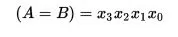
Simply check if all bits are the same for equality!
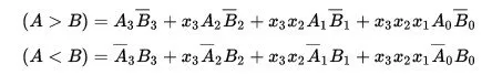
If you think about those other expressions for a while you will see that it uses the same logic that we use when comparing numbers by ourselfs. It starts out with the most-left bit and continues on going to the right and also includes a AND Operation for the bits to the left of the bit we are checking to see if they are the same, cause else the result is not right! That way we check each possible combination.
So, our Code for the 4-bit Comparator looks like this:
library ieee;use ieee.std_logic_1164.all;entity digital_comparator_dataflow isport( a: in std_logic_vector(3 downto 0); b: in std_logic_vector(3 downto 0); equal: out std_logic; greater: out std_logic; less: out std_logic);end digital_comparator_dataflow;
architecture arch of digital_comparator_dataflow is
signal x, not_a, not_b: std_logic_vector(3 downto 0);
begin x(3) <= a(3) xnor b(3); x(2) <= a(2) xnor b(2); x(1) <= a(1) xnor b(1); x(0) <= a(0) xnor b(0); not_a <= not a; not_b <= not b; equal <= x(3) and x(2) and x(1) and x(0); greater <= (a(3) and not_b(3)) or (x(3) and a(2) and not_b(2)) or (x(3) and x(2) and a(1) and not_b(1)) or (x(3) and x(2) and x(1) and a(0) and not_b(0)); less <= (not_a(3) and b(3)) or (x(3) and not_a(2) and b(2)) or (x(3) and x(2) and not_a(1) and b(1)) or (x(3) and x(2) and x(1) and not_a(0) and b(0));end arch;You can see that the Line of Code for the greater and less expressions are gigantic, because of the many checks! We simply have to follow the Expressions and that way we will have a value of '1' on either of the outputs.
We could also write this Circuit using Gates in Structural VHDL and this would look even crazier! Supposing the Multi-Gates are already implemented the Code for the 4-bit Comparator only would look like this:
library ieee;use ieee.std_logic_1164.all;entity digital_comparator_structural isport( a: in std_logic_vector(3 downto 0); b: in std_logic_vector(3 downto 0); equal: out std_logic; greater: out std_logic; less: out std_logic);end digital_comparator_structural;architecture arch of digital_comparator_structural is component xnor2_gate port( a, b: in std_logic; c: out std_logic ); end component;
component and2_gate port( a, b: in std_logic; c: out std_logic ); end component;
component and3_gate port( a, b, c: in std_logic; d: out std_logic ); end component;
component and4_gate port( a, b, c, d: in std_logic; e: out std_logic ); end component;
component and5_gate port( a, b, c, d, e: in std_logic; f: out std_logic ); end component;
component or4_gate port( a, b, c, d: in std_logic; e: out std_logic ); end component;
component not_gate port( a: in std_logic; b: out std_logic ); end component;
signal x, not_a, not_b: std_logic_vector(3 downto 0); signal and2_to_greater: std_logic; signal and3_to_greater: std_logic; signal and4_to_greater: std_logic; signal and5_to_greater: std_logic; signal and2_to_less: std_logic; signal and3_to_less: std_logic; signal and4_to_less: std_logic; signal and5_to_less: std_logic;
begin
not1: not_gate port map(a(3), not_a(3)); not2: not_gate port map(a(2), not_a(2)); not3: not_gate port map(a(1), not_a(1)); not4: not_gate port map(a(0), not_a(0)); not5: not_gate port map(b(3), not_b(3)); not6: not_gate port map(b(2), not_b(2)); not7: not_gate port map(b(1), not_b(1)); not8: not_gate port map(b(0), not_b(0)); xnor1: xnor2_gate port map(a(3), b(3), x(3)); xnor2: xnor2_gate port map(a(2), b(2), x(2)); xnor3: xnor2_gate port map(a(1), b(1), x(1)); xnor4: xnor2_gate port map(a(0), b(0), x(0)); and2_1: and2_gate port map(a(3), not_b(3), and2_to_greater); and3_1: and3_gate port map(x(3), a(2), not_b(2), and3_to_greater); and4_1: and4_gate port map(x(3), x(2), a(1), not_b(1), and4_to_greater); and5_1: and5_gate port map(x(3), x(2), x(1), a(0), not_b(0), and5_to_greater); and2_2: and2_gate port map(not_a(3), b(3), and2_to_less); and3_2: and3_gate port map(x(3), not_a(2), b(2), and3_to_less); and4_2: and4_gate port map(x(3), x(2), not_a(1), b(1), and4_to_less); and5_2: and5_gate port map(x(3), x(2), x(1), not_a(0), b(0), and5_to_less);
and_equal: and4_gate port map(x(3), x(2), x(1), x(0), equal); or_greater: or4_gate port map(and2_to_greater, and3_to_greater, and4_to_greater, and5_to_greater, greater); or_less: or4_gate port map(and2_to_less, and3_to_less, and4_to_less, and5_to_less, less);end arch;That was for all that maybe said: "well the Dataflow Lines are to complicated". Then yeah check out how complicated and connected the Structural Representation is! Off course we could also do a Behavioral Representation, but I think that was enough for you today :P
And this is actually it!
Next time we will combine those Components inside of a VHDL Structural Representation that will be our ALU Circuit. The Boolean Operations will be handled inside of the architecture using simple Gate Components and you will also see how we will use the Input of two 4-bit Comparators to compare 8-bit numbers!
Until next time...Bye!