Hello my friends! Today we will get into the differences between the Different Descriptions/Models that we can write a Circuit. I will first explain what Behavioral, Dataflow and Structural need to be implemented in VHDL Code and then we will get into some Example Circuits that we will write in all 3 ways for you to see the difference! So, let's get started!
We actually already talked about Behavioral and Dataflow before, but for sake of coverage I will write all 3 so that you can have all in one place! Also, this time you will understand the difference a little better inside of the Examples Section.
Behavioral Description Model:
In this Model we follow the Truth Table of a Circuit. So, we will have a if or case statement inside of a process or a when-else, with-select statement for each output inside of the architecture. We mostly prefer processes!
We can write a Behavioral Description of a NAND Gate like that:
library ieee;use ieee.std_logic_1164.all;entity nand2 isport( a, b: in std_logic; c: out std_logic);end nand2;architecture arch of nand2 is begin process(a, b) begin if a='1' and b='1' then c <= '0'; else c <= '1'; end if; end process;end arch;You can see that we don't need all different kinds of inputs, but we simply use only those that give us '1' or '0' and put the rest into the else part! That way we will have a smaller code, prefering the Max or Minterms depending on their count.
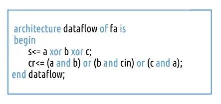
Dataflow Description Model:
A Dataflow Description is based on Boolean Functions/Expressions for each Output. So, we will simply assign the Outputs directly having the Inputs inside of Expressions that give us the Output values directly.
So, a AND-3 Gate for example looks like this in Dataflow:
library ieee;use ieee.std_logic_1164.all;entity and3_gate isport( a, b, c: in std_logic; d: out std_logic);end and3_gate;
architecture arch of and3_gate is begin d <= a and b and c;end arch;You can see that we simply assign the Output to the corresponding Expression that contains the Inputs! Off course this Expression can get complicated (we will have such a Example in the Example Section) and we can also have more than one Outputs!
Structural Description Model:
The most descriptive Model is without any doubt the Structural Description. To use this Model we need to know the Structure/Gating of the Circuit. We will have to write a VHDL Description for all the Gates and Sub-Circuits that the Structural Model Circuit contains. All this Circuits will be used as Components.
In this Model we use a new statement called port map. Using this statement we connect the Sub-Circuits together having Signals/Cables in between them, the Inputs and the Outputs! Suppose we have the AND-3 Gate from before, that contains 3 Inputs and 1 Outputs and that we have it as a Component inside of our Circuit. Then the port map will need 4 Attributes that will be the signals assigned to the Inputs/Outputs, that can also be a Input/Output of the Circuit. Suppose the Inputs/Outputs have the same names in the Structural Model. So, this would look like this:
label: and3_gate port map (a, b, c, d);
You can see that we use a label, the Component Name and after that the Attributes (Input/Output Mapping).
So, to recap really quick, a Structural Model contains Components (Sub-Circuits) that are Port Mapped using In-Between Signals, Inputs and Outputs to construct the Circuit.
Examples:
To understand the differences a little better, let's write some Circuits in all 3 Models! I will use 2 Examples. The first one will contain simple Gating and 1 Output, and the second will contain even simpler Gating but more Outputs!
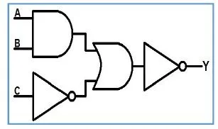
Example 1:
The Circuit looks like this:
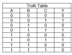
Testing out all Input Values I end up with this Truth Table:
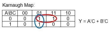
Then the Karnaugh Map and Function look like this:
Using those 3 Things we can then write down the 3 Models like that:
Behavioral:
library ieee;use ieee.std_logic_1164.all;entity c_behavioral isport( A, B, C: in std_logic; Y: out std_logic);end c_behavioral;
architecture arch of c_behavioral isbeginprocess(A, B, C)beginif (C='0') then Y <= '0';elsif (A='1' and B='1') then Y <= '0';else Y <= '1'; end if;end process;end arch;We simply follow the Truth Table here!
Dataflow:
library ieee;use ieee.std_logic_1164.all;entity c_dataflow isport( A, B, C: in std_logic; Y: out std_logic);end c_dataflow;
architecture arch of c_dataflow issignal not_a: std_logic;signal not_b: std_logic;beginnot_a <= not A;not_b <= not B;Y <= (not_a and C) or (not_b and c);end arch;I don't like to complex Expressions and so I create In-Between Signals!
Structural:
You have to write and compile all Components before compiling and simulating the main Circuit.
The Components can be written in any way and I used those:
Not Gate
library ieee;use ieee.std_logic_1164.all;entity not_gate isport( a: in std_logic; b: out std_logic);end not_gate;
architecture arch of not_gate isbeginb <= not a;end arch;Or Gate
library ieee;use ieee.std_logic_1164.all;entity or2_gate isport( a, b: in std_logic; c: out std_logic);end or2_gate;
architecture arch of or2_gate isbeginc <= a or b;end arch;And Gate
library ieee;use ieee.std_logic_1164.all;entity and2_gate isport( a, b: in std_logic; c: out std_logic);end and2_gate;
architecture arch of and2_gate isbeginc <= a and b;end arch;The main Circuit looks like this:
library ieee;use ieee.std_logic_1164.all;entity c_structural isport( A, B, C: in std_logic; Y: out std_logic);end c_structural;
architecture arch of c_structural is
component not_gateport( a: in std_logic; b: out std_logic);end component;
component or2_gateport( a, b: in std_logic; c: out std_logic);end component;
component and2_gateport( a, b: in std_logic; c: out std_logic);end component;
signal and1_to_or1: std_logic;signal not1_to_or1: std_logic;signal or1_to_not2: std_logic;
begin
and1: and2_gate port map(A, B, and1_to_or1);not1: not_gate port map(C, not1_to_or1);or1: or2_gate port map(and1_to_or1, not1_to_or1, or1_to_not2);not2: not_gate port map(or1_to_not2, Y);
end arch;You can see that the Code becomes much larger, but we have a much bigger influence on the Connections between the Gates/Sub-Circuits and the whole Layout/Gating of our Circuit in general!
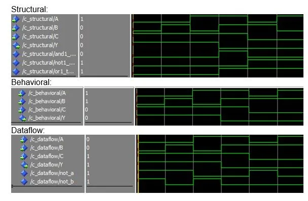
Simulating the Circuits in Modelsim we can see that they do the same exact thing!
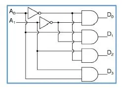
Example 2:
The Circuit looks like this and is a Encoder:
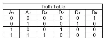
The Truth Table can be found out easily by testing out the 4 Input Combinations and looks like this:
We don't need K-Map but get the Functions directly more easily and they look like that:

The 3 Models can be written simply by using all those Things we have on top!
Behavioral:
This time we will have to use all possible input combinations and can't skip any if them
library ieee;use ieee.std_logic_1164.all;entity f_behavioral isport( A: in std_logic_vector(1 downto 0); D: out std_logic_vector(3 downto 0));end f_behavioral;
architecture arch of f_behavioral isbeginprocess(A(1), A(0))beginif (A(1 downto 0)="00") then D(3 downto 0) <= "0001";elsif (A(1 downto 0)="01") then D(3 downto 0) <= "0010";elsif (A(1 downto 0)="10") then D(3 downto 0) <= "0100";else D(3 downto 0) <= "1000";end if;end process;end arch;Dataflow:
This representation is also not so difficult and I will again use In-Between Signals
library ieee;use ieee.std_logic_1164.all;entity f_dataflow isport( A: in std_logic_vector(1 downto 0); D: out std_logic_vector(3 downto 0));end f_dataflow;
architecture arch of f_dataflow issignal not_A1: std_logic;signal not_A0: std_logic;beginnot_A1 <= not A(1);not_A0 <= not A(0);D(0) <= A(1) nor A(0);D(1) <= not_A1 and A(0);D(2) <= A(1) and not_A0;D(3) <= A(1) and A(0);end arch;Structural:
Let's skip the Components, cause we already have them set up and just write the structural model!
library ieee;use ieee.std_logic_1164.all;entity f_structural isport( A: in std_logic_vector(1 downto 0); D: out std_logic_vector(3 downto 0));end f_structural;
architecture arch of f_structural is
component not_gateport( a: in std_logic; b: out std_logic);end component;
component and2_gateport( a, b: in std_logic; c: out std_logic);end component;
signal not1_to_and1: std_logic;signal not2_to_and1: std_logic;signal not1_to_and3: std_logic;signal not2_to_and2: std_logic;
begin
not1: not_gate port map(A(0), not1_to_and1);not1_to_and3 <= not1_to_and1;not2: not_gate port map(A(1), not2_to_and1);not2_to_and2 <= not2_to_and1;and1: and2_gate port map(not1_to_and1, not2_to_and1, D(0));and2: and2_gate port map(not2_to_and2, A(0), D(1));and3: and2_gate port map(A(1), not1_to_and3, D(2));and4: and2_gate port map(A(1), A(0), D(3));end arch;You can see that for this Circuit the Structural Representation was not so bad and also gives us more control so that we have less signals/cables inside of our Circuit!
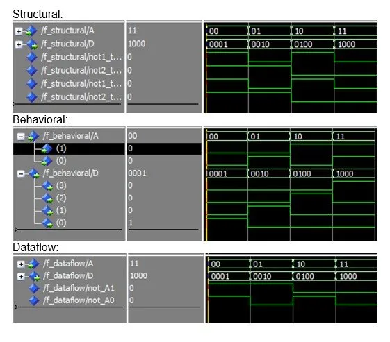
The Results for all those Circuits are again the same and look like this in Modelsim:
And this is actually it! Hope you enjoyed this post!
Next time in VHDL we will get into Sequential Circuits that are much more interesting to simulate and work with in Modelsim!
Until next time...Bye!