Hello its me again! Today we will talk about NAND and NOR Gates, that are the so called Universal Gates! I will start talking about the same stuff as in Basic Gates and then I we will get into what makes them universal! So, let's get straight into it!
NAND Gates:
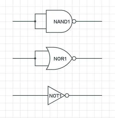
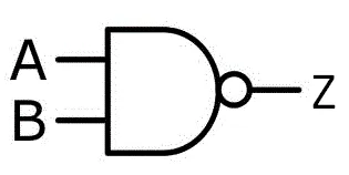 NAND Symbol
An NAND Gate is an AND Gate with inverted output (like having an AND Gate and a NOT Gate one after another). So, we have an output of 0 when both inputs are same, and an output of 1 in any other case! I like symbolizing it in an Function using (AB)', that basically means inverted AND!
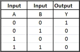
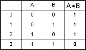 Truth Table
In the truth table we see exactly what I meant. It is the exact inverse of an AND Gate!
NOR Gates:
 NOR Symbol
A NOR Gate is a inverted OR Gate. So, we have the exact opposite results of an OR Gate. When Both are 0 output 1, else 0. I like symbolizing it using (A+B)', that basically means inverted OR.
 Truth Table
We can again see the exact same as before. The Truth Table is the exactly inverse of an OR Gate!
So, now let's get into why we call them "Universal Gates".
Universal Gates:
The NAND and NOR Gates are called Universal Gates, cause using only one Gate of those 2 types of Gates we can create any type of Circuit. To make it more clearly, we can use NAND (or NOR) Gates and turn them into any other Gate when putting them together. So, using for example 1 NAND (or NOR) Gate and having both Inputs be the same, we successfully create an NOT Gate and so on...
The way we arrange those Gates into others is called NAND and NOR Logic, for each one of those specific. I will now get into how we arrange them to form the Basic Gates we talked about last time and each other (form NAND using NOR and vise versa).
So, let's start out with NAND Logic!
NAND Logic:
NOT:
A NOT gate is made by joining the inputs of an NAND Gate, cause when having those 2 be the same we use only those 2 parts of the Truth Table and succesfully create an NOT Gate(0->1 and 1->0).
 NOT using 1 NAND
AND:
A AND gate is the inverse of an NAND Gate, so we will put an NOT Gate after the NAND Gate, but this NOT Gate will be the NOT Gate using NAND we talked earlier.
 AND using 2 NAND's
OR:
An OR Gates Truth Table when compared to the NAND Gates one has only one change, we have Output of 0 when Inputs are both 1 and Output of 1 when Inputs are both 0, so we will simply Invert the Inputs of an NAND Gate, using the NOT Gate we used previously.
 OR using 3 NAND's
NOR:
I think it's self explained. I will simply use the OR Gate we made previously and invert it using an NOT Gate that we also made.
 NOR using 4 NAND's
XOR:
To create an XOR Gate we will use a similar concept to the OR Gate's one. We will not simply invert the Inputs of an NAND Gate, but use another one before. So, the 2 invertion Gates will now have 1 Input directly and 1 Input that comes from another NAND Gate, so that we end up at the results of an XOR Gate. That way we change the Truth Table from the OR Gate a little bit, so that the Output when both are the same is not 1 anymore, but 0!
 XOR using 4 NAND's
XNOR:
Again self explained. We simply invert the XOR Gate from before, cause the XOR and XNOR Gate have inverted Truth Tables!
 XNOR using 5 NAND's
NOR Logic:
NOT:
A NOT gate is again made by joining the inputs of an NOR Gate, the same way we did in with an NAND Gate!
 NOT using 1 NOR
OR:
An OR Gate can be made by simply inverting the Outputs of a NOR Gate using one NOT Gate (that use NOR).
 OR using 2 NOR's
AND:
An NOR Gate gives an Output of 1 when Inputs are 0, else 1. So, we will invert the Inputs the same way we did it for the OR Gate when using NAND Gates!
 AND using 3 NOR's
NAND:
A NAND is self explained. We invert the AND Gate we made previously, using an NOT Gate that we also made.
 NAND using 4 NOR's
XNOR:
An XNOR Gate can be made by setting up the NOR's the same way we set them up for XOR's using NAND Gates. (I will not gate into more than that)
 XNOR using 4 NOR's
XOR:
An XOR Gate can be made by inverting the Output of an XNOR Gate (I like thinking about it that way), but there are also other ways. The one that the most use minimizes the propagation delay and is this one:
 XOR using 5 NOR's
Which should I use?
In University they actually tell us which one we should use in which Task. So, you should know both of them. And it's actually easy to remember! You can easily find mirror's from NAND to NOR and vise versa. I like thinking about it like that:
- NOT's are basically the same and don't depend of NAND or NOR
- An OR Gate using NOR looks the same as an AND Gate using NAND
- An OR Gate structure using NAND looks the same as the one that makes an OR Gate using NAND
- An NAND using NOR structure looks the same as the NOR using NAND structure
- An XOR using NAND looks the same as an XNOR using NOR
So, the only difficult one is the change of the XOR using NOR, if you want to use the most efficient one!
Example:
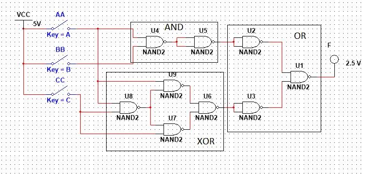
Create a Circuit using NAND Gates, that implements the following function:
F(A, B, C) = AB + A⊕C
So, we have to create an OR Gate with Inputs of an AND Gate and an XOR Gate!
We end up with the following Circuit that I made using Multisim (we will get into that later on):
This is the end of today's post! Hope you enjoyed it!
Next time we will get into how we translate a Function into a Circuit and I will also talk about Logic Gates that have more than 2 Inputs!
Until next time..Bye!