
Hi it's a me Drifter Programming! Today we will talk about the Implementation of Multiplexer, Encoder and Decoder Circuits in Multisim! You can check out the Theory for all that here and we already did some Circuits there, but I have some more and I will also get more in depth into the implementation part of the Multisim Software. So, let's get straight into it!
Multiplexers:
A Multiplexer is a Circuit that selects one of 2^n inputs from n selection lines and gives 1 Output, as you might remember from Theory! So, we have 2^n-to-1 MUX's. Let's make another example this time, where we will not have 3 Variables, but 4 Variables instead. That way we will have to use a 8-to-1 MUX! We will have 3 Selection Lines and 8 "I Inputs".
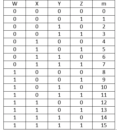
Suppose we have a Circuit that gives an Output of 1, only when the Input Combination Value can be divided perfectly by 3. Our Input will contain 4 Binary Digits and so we can have only numbers up to 1111 that is 15 in the decimal system. So, our Truth Table will contain 1's only in 3, 6, 9, 12, 15 that are in binary 0011, 0110, 1001, 1100, 1111. That way our Truth Table looks like this:

Let's take B, C and D as selection Lines and form groups of 01 for A. That way we will fill the following Array that will give us the "I" Inputs for our 8-to-1 MUX:
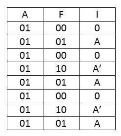
So, I0 = 0, I1 = A, I2 = 0, I3= A', I4 = A, I5 = 0, I6 = A' and I7 = A.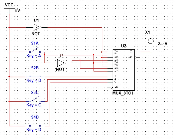
And will will put B, C, D as selection Lines and all the "I" Inputs as Input to the 8-to-1 MUX using NOT Gates if needed for inversion! That way the output of the MUX will follow our Truth Table exactly!
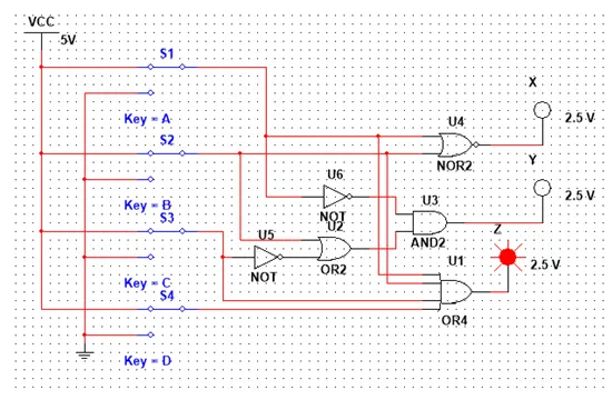
So, our Circuit looks like this and let's also test it out for some values:
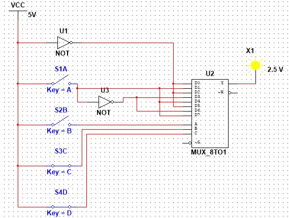
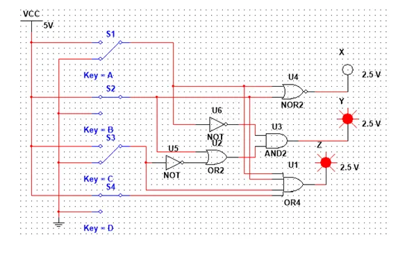
0011 equals to 3 and so the Output is 1
0101 equals to 5 that is not divisible with 3 and so the Output is 0
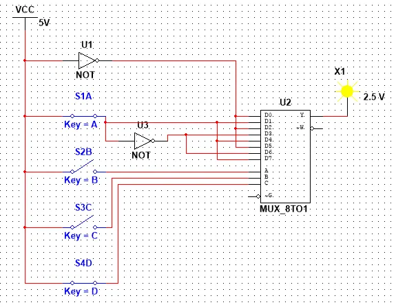
1001 equals to 9 that is divisible with 3 and so the Output is 1
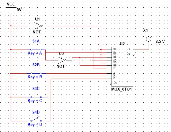
1110 equals to 14 that is not divisible with 3 and so we have an Output of 0
I hope that you know understood the concept of Multiplexer's even more! Our Circuit would become much bigger if we created it without a Sub-Circuit 8-to-1 MUX, but using only Gates!
Encoders:
Encoders compress information from multiple lines into a smaller number of inputs! We mostly use Priority Encoders where only the most left input gets selected and so, we talk off 2^n-to-n Encoders! The example we had in Theory was pretty good and I'm thinking off explaining it a little more this time instead of getting into a new one!
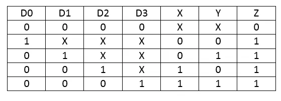
In Theory we had the following Truth Table for a 4x2 Priority Encoder:
Let's get the Output Functions using Karnaugh Map:
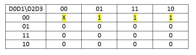
X = D0'D1' = (D0+D1)'
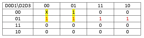
Y = D0'D2' + D0'D1 = D0' (D1 + D2')

Z =D0 + D1 + D2 + D3
As you can see I used the X's as I wanted them to be (0 or 1) and also grouped some Minterms more than 1 times to get the best result!
So, our Circuit looks like this and let's test it out for different inputs:

Having none of the Inputs be 1 we have Z = 0 that means our Output is invalid!
Having all be 1, D0 has the highest priority and so we end up with the result X = Y = 0.
Having D1 = D3 = 1 and D0 = D2 = 0, D1 has the highest priority and so we have the Output X = 0, Y = 1.
You can think off what happens in any other Case! So, using an Priority Encoder we can minimize our Data having the Output have specific values on each input combination, checking only the input with the most priotity!
Decoders:
Decoders are the opposite of Encoders and using them we can convert our Input backwards! We already had a pretty good example in Theory and I'm thinking of something special for this post. So, let's implement a 4x16 Decoder using two 3x8 Decoder's (that we already used last time)!
A Truth Table for a 4x16 Decoder looks like this:
I will use X, Y, Z as Inputs for both Decoders and W as an Enable Signal for the two 3x8 Decoder's that contain a Enable Input! That way the first Decoder will be active for the minterms from 0 to 7 and the second Decoder will be active for the minterms from 8 to 15!
Let's test this out using two easy Function F = Σ(0, 1) and G = Σ(8, 9) where we will only have to switch W on and off to check if our Enable stuff really works.
So, our Circuit looks like this:
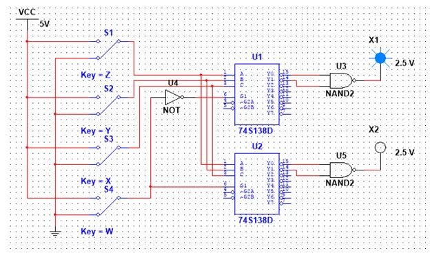
With Input 0000 the top Decoder gives an Output of 1, cause he is enabled with W = 0 that gets inverted with a NOT Gate to 1!

With Input 1000 the bottom Decoder gives an Output of 1, cause he is enabled with W = 1!
So, you can now see a little bit better how such an Decoder works and this is actually it!
Hope you enjoyed this post!
Next time in Logic Design we will get into Statetable Simplification and Implementation with one-hot Encoding and after that I will implement a Sequential Circuit in Multisim using D Flip Flops!
Until next time...Bye!