Hey! It's me. This time in Logic Design we will implement some of the Logic Gates we talked off in Theory inside of Multisim. That way you will get more familiar with the Software and we will also proof the Truth Tables of many Gates! So, without further do. Let's get started!
Basic Gate Implementation:
Let's start off with some off the Basic Gates. I will implement first a simple NOT Gate, then a OR Gate and lastly a XOR Gate (I already used a AND Gate in the last post if you want to check it out too).
NOT Gate:
As you might remember a NOT Gate works as a Inverter, so what we will see inside of MultiSim is that the Output will have the opposite value of the Input.
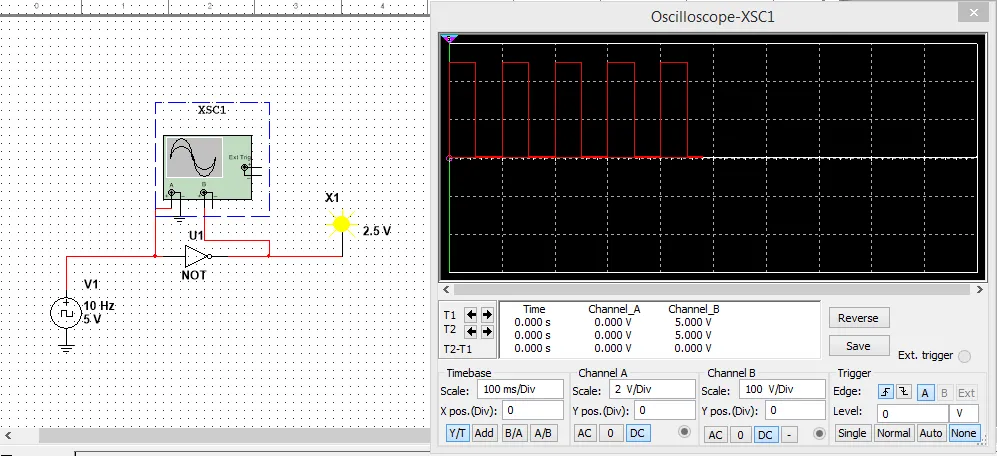

I have the Input be a Clock and connected after that a NOT Gate that leads to an Probe. I connected the A part of the Oscilloscope before the NOT Gate to check the Input value and have the Probe give me the Probe/Output value. As you can see the Output is 1 when the Input is 0, and the Output is 0 when the Input is 1. That proofs that a NOT Gate works as a Inverter!
OR Gate:
An OR Gate gives a Output of 1 when either of the 2 Inputs has a value of 1, else it gives 0. We will this time use switches and constant voltage for the Inputs, so that you can see how we can do it in another way!
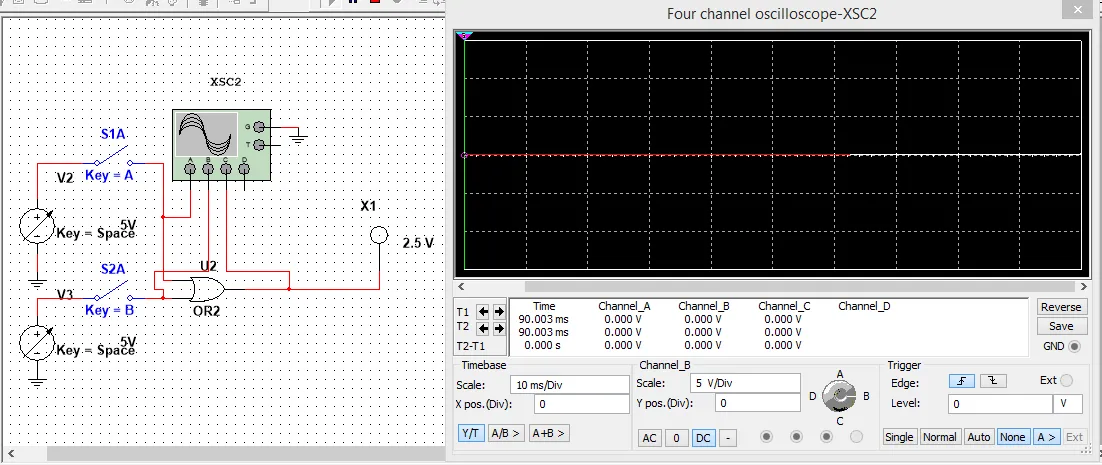

We again see that the Output is 0 only when both Switches are open (Input -> 0). In any other case the Output is 1!
XOR Gate:
A XOR Gate gives an Output of 1, when the Inputs differ as you can hopefully remember(!). So, this time let's implement it using 2 Clocks with different Frequencies!
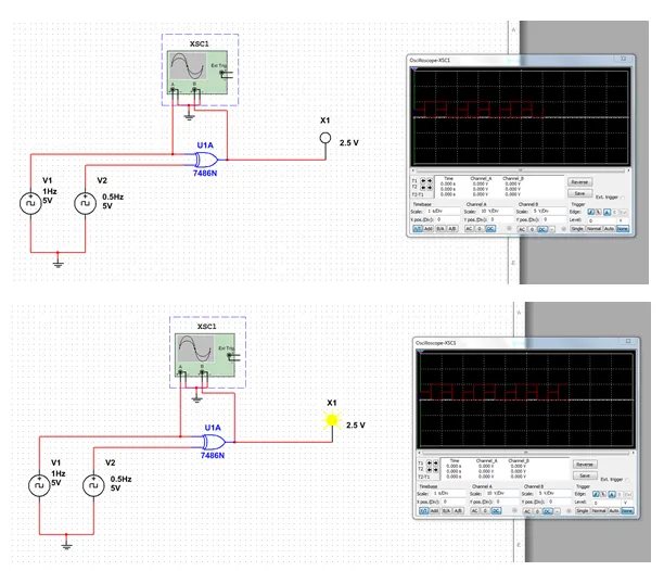
As you can see from the Waveform in the Oscilloscope, where I put different Scales for each different Input, the Probe lights only when the Outputs are 0 and 1 or vise versa that means they differentiate!
Universal Gate Implementation:
Let's implement now some Gates using Universal Gates to proof the Gating I showed you in Universal Gates! I will implement a OR and a NOR Gate using NAND Gates.
OR Gate:
We implemented a OR Gate already today and as you remember the Output is 0 only when both Inputs are 0. I will implement it using two Clocks of different Frequencies and use a Oscilloscope to check the Inputs!
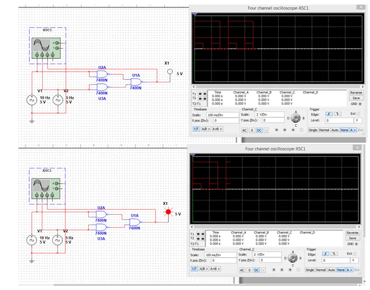
As you can see the Output is 0 only when both Inputs are 0, else it's 1.
NOR Gate:
To implement a NOR Gate we will have to invert the OR Gate we made previously. If you remember a NOT using NAND or NOR is made by joining the Inputs. We will use the same structure as before.

As you can see the Output is only 1 when both Inputs are 0, else the Outputs is 0. So, we really have inverted the OR Gate successfully :)
Multi-Input Gate Implementation:
Let's now lastly, implement a Multi-Input Gate. I think the best one would be a XOR or XNOR Gate so that we check our Rule of odd and even 1's. So let's implement a XOR 4 Gate and see if it's true!
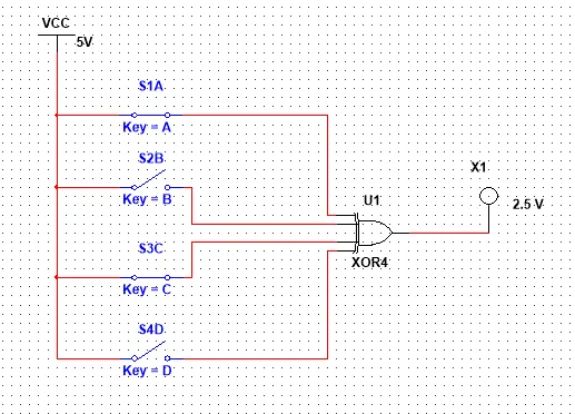

With 2 Inputs active that are a even number the Outputs is 0 (that same happens with none or all)


Only when 1 or 3 Inputs are 1, so that we have a odd number of 1's the Output becomes 1!
So, we proofed our Rule of 1's :)
This is the end of this post! Hope you enjoyed it!
Next time in Multisim Implementation I will create simple Circuits that those Gates, starting off with a Truth Table, doing Karnaugh Map or Boolean Algebra and then implementing it in a Circuit!
Until next time...Bye!