
Hello again. Today we will talk about the Basic Logic Gates that we use in Circuits. I will talk about NOT, OR, AND, XOR and XNOR Gates and I will leave NOR and NAND gates for the next time, cause they are the so called Universal Gates and have some more tricks in there sleeve! We will talk about how we symbolize them inside of a logic circuit, how we notate them inside of a circuit function and they Truth Tables. So, without further talk let's get straight into them!
Gates:
Logical Gates are the so called fundamental parts of a logical circuit. Using those we can create any circuit we like and all can have different functionality. The Circuits that we use inside of other Circuits are also made up of those Basic or Universal Logic Gates, but we just use the Inputs/Outputs of those. So, we "ignore" the structure of those in some way, to make things simpler for us! I will show you when we are finished with Theory (we have a lot of posts until then) how we implement all those and how easy it is to make advanced circuits using other circuits that are already made!
So, after this small introduction let's start talking about those 5 Basic Gates one by one!
NOT Gate:
 NOT Symbol
A NOT Gate inverts the Voltage of an given Input. So, we use it when we want 0 to become 1 or 1 to become 0. We can notate NOT in many different Ways. I will use an ', cause I already started that way and it's easier in steemit! But, the right way is an '-' on top of the variable and you should do it that way on paper.
 Truth Table
The Truth Table is pretty easy and describes exactly what it does! 1 -> 0 and 0 -> 1.
OR Gate:
 OR Symbol
An OR Gate checks the two Inputs and when either one of the two has a value of 1 the output will be 1, if both are 0 then we have an output of 0! We use a '+' Notation to describe an OR Gate inside of an Function!
 Truth Table
The Truth Table describes exactly what I told you. Only when both are 0 we have output of 0, else we have 1!
AND Gate:
 AND Symbol
An AND Gate gives an Output of 1 only when both inputs have a value of 1. We Notate it using an multiplication symbol '*' or nothing (the way we notate multiplication in high school).
 Truth Table
The Truth Table again describes exactly what I told you! only when both are 1 we have Output 1, else 0!
XOR Gate:
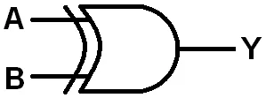 XOR Symbol
An XOR Gate or Exclusive-OR Gate checks if the Input values differ. So, we have an Output of 1 only when the Inputs differ, if they are same we have an Output of 0). We use the ⊕ Symbol or the word XOR as Notation inside of an function.
 Truth Table
The Truth Table describes again exactly what I told you!
XNOR Gate:
![]() XNOR Symbol
XNOR Symbol
An XNOR or XAND Gate is the exactly opposite of an XOR Gate! So, it returns an Output 0f 1 when the Inputs are the same and an Output of 0 when they differ! The Notation is either an XOR Gate and NOTified like that:
(A⊕B)' or we use the XAND Symbol  , but I will use the NOTified one!
 Truth Table
The Truth Table describes again exactly what it does and you can see that it is the opposite of the XOR Gate's one.
This is the end of this post. Hope you enjoyed it and learned something new (or refreshed your knowledge)!
Next time (in Logic Design) we will talk about the Universal Gates and after that I will show you how you get from Function to Circuit! I will try uploading also other stuff in between of our Logic Design posts and I have also some ideas ready already!
Until next time...