Almost ten years ago, back when I was still teaching basic electronics. I wanted to show one of my student an actual application of what I’ve been learning. So, I need to come up with an idea that could capture his interest to yearn for more advanced topics.
My student at that time is a high school science teacher. He wants to advance his electronics knowledge that is why he came to me.
We need a project that would not only capture his interest but his students as well. I am sure that if we successfully make it that he will most probably teach it also to his students.
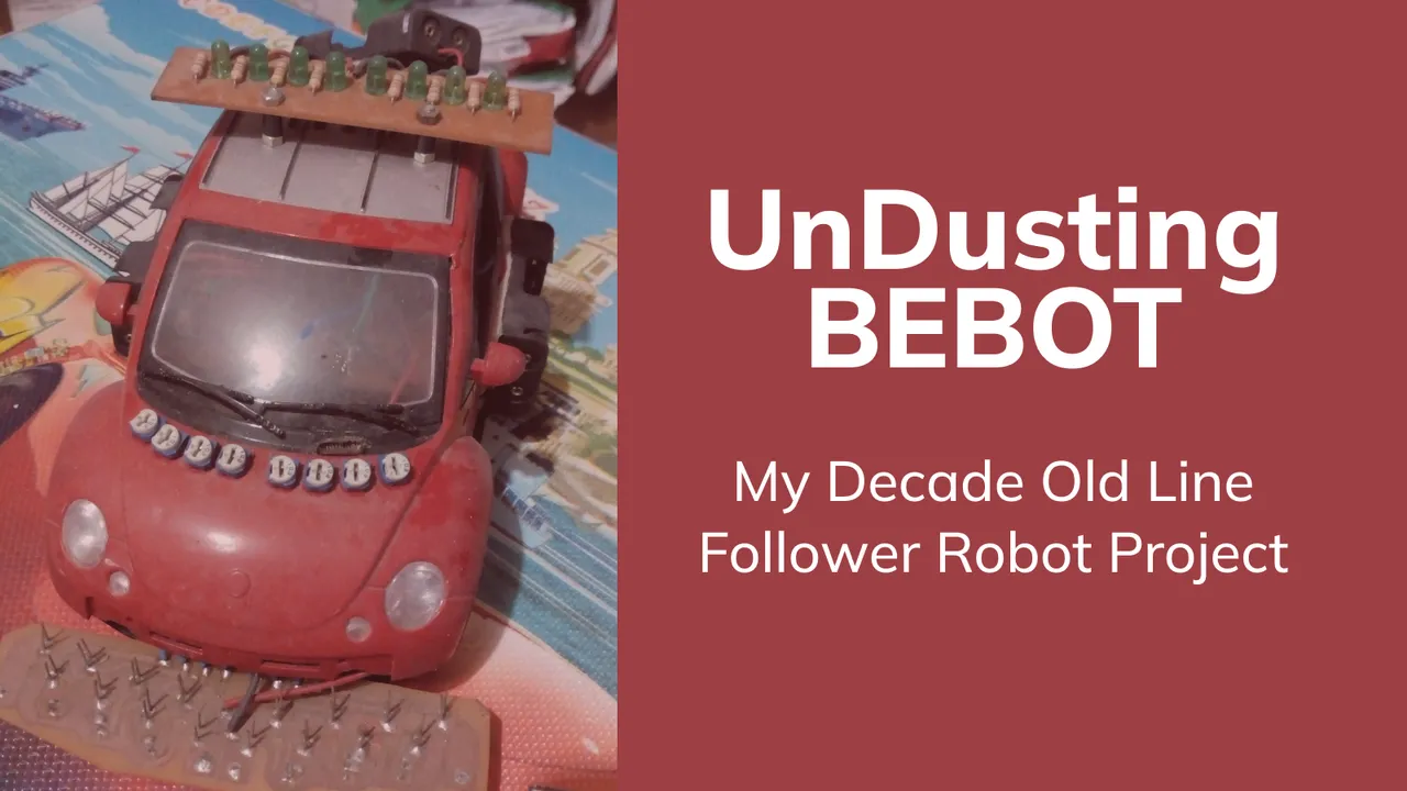
The first thing that came into my mind at that time was a LINE FOLLOWER ROBOT.
I decided on building one without using any microcontroller.
There would be no pre-assembled sensors nor motor driver modules.
Side Note: What is a Line Follower Robot?
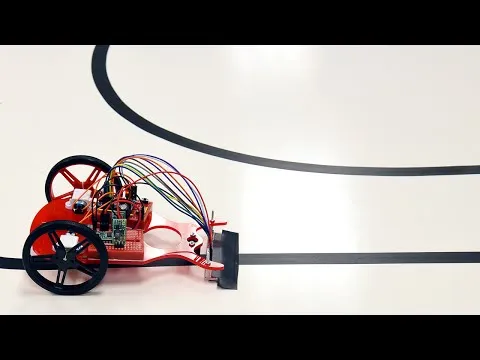
A line follower robot is a type of robot that is specifically designed to follow a printed track.
Below is a video that I've found on Line Followers in action. The line followers in the video uses programmable microcontrollers and modules.
Circuit design is a little too advance for him so I handled it.
I used discrete components so that I can discuss how it works as a continuation of our previous topics.
What I want him to design and build is the Logic Unit (AI) of our line follower using basic Logic Gates.
I am aiming for simple functionality (AI) just to make him appreciate what we had learned.
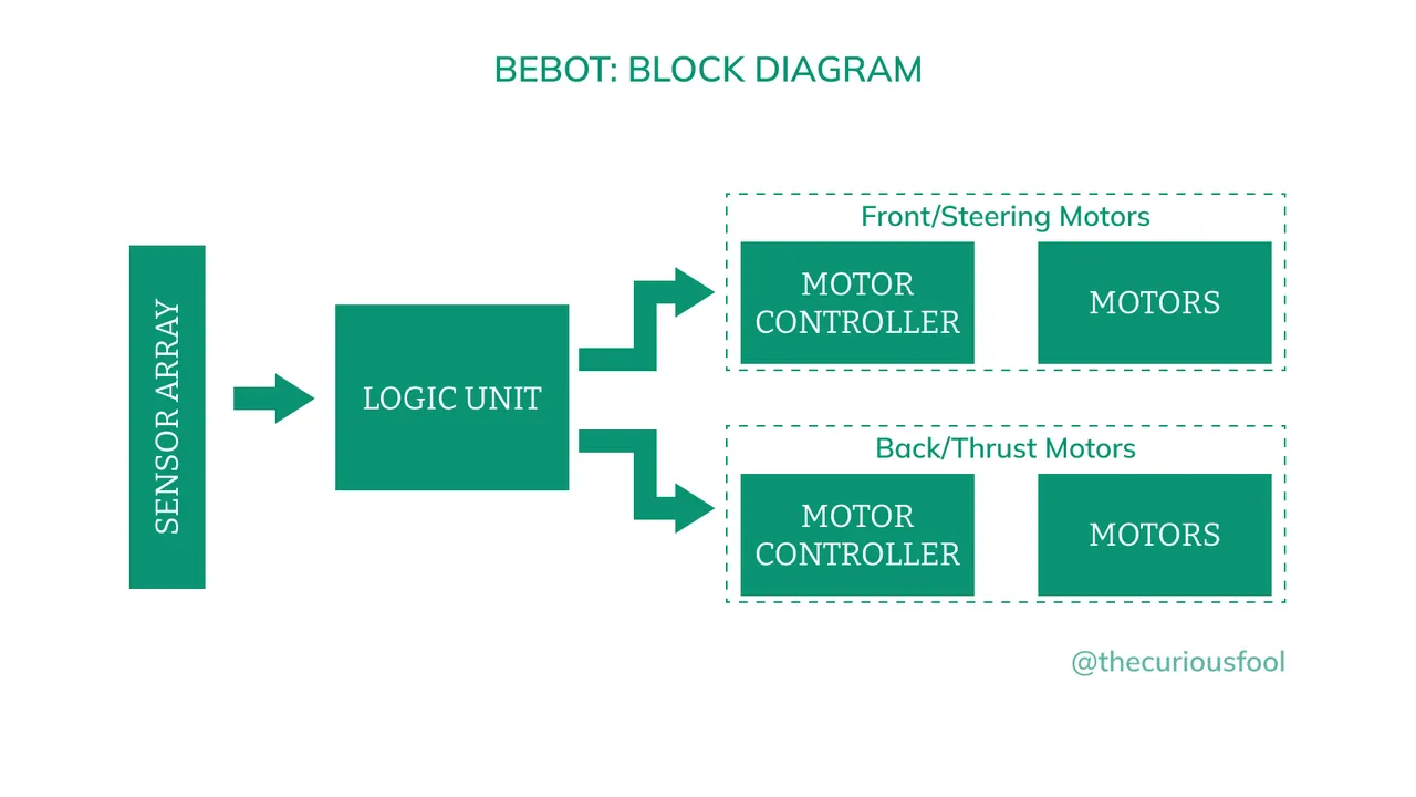
Design Overview
Motors
There would be three DC motors, two for the thrust and one for steering.
The thrust motors will be responsible in moving the line follower forward and backwards.
The steering motor will function to direct in which direction the car should move.
Motor Controllers
This will be the bridge between the logic unit and motors. The motor controllers will control in which the motors will turn. One controller for steering and one controller for the thrust motors.
Sensors
The sensors will be used to detect the lines. They will serve as the “eyes” of the line follower. The output of the sensors would then be fed to the logic unit for processing and interpretation.
Logic Unit
The brain of the line follower. It will analyze inputs being “seen” by the sensors, process it and decides in which directions the motors should move.
The Actual Hardware
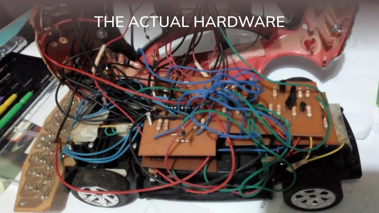
The Main Body and the Motors.
There is no nearby electronic store, at that time, that sells parts for line follower parts so I have to repurpose an old RC car. I removed the built-in circuits and all other parts except for the motors, wheels and the main body.
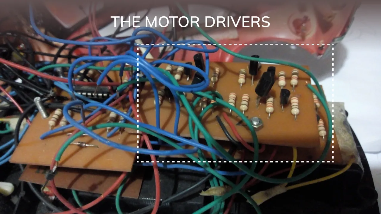
The Motor Drivers
The motor drivers or controllers are made with a simple H-Bridge circuit.
It’s been too long since I made my calculations so I cannot give you the exact schematic diagram and parts list. Here is a rough draft of what I can remember:
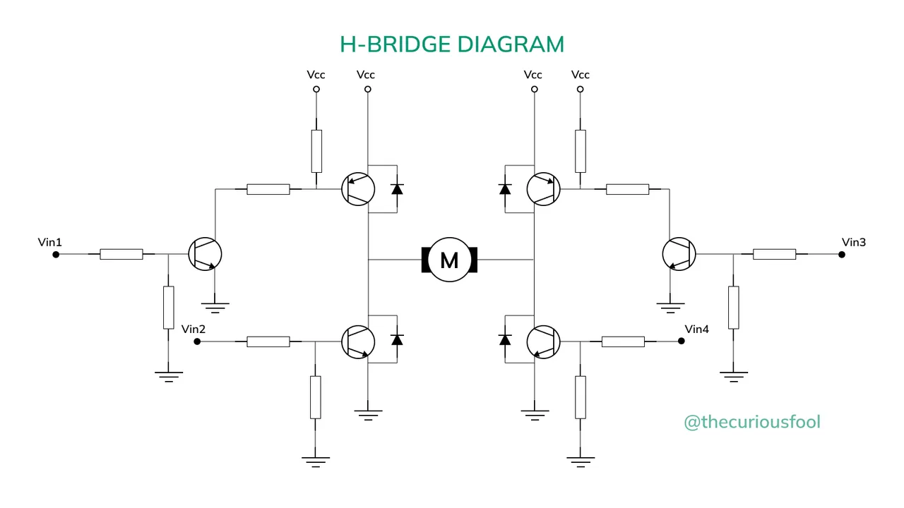
The motor drivers controls the direction in which the motors would spin. This can be easily achieved by changing the direction of the current.
The Line Sensors
I used a simple IR RX/TX pair. I could have used an ordinary LED/photo-resistor pair but I am worried of external light interference. It might be too sensitive to the environment and artificial lightings.
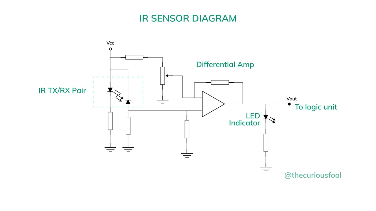
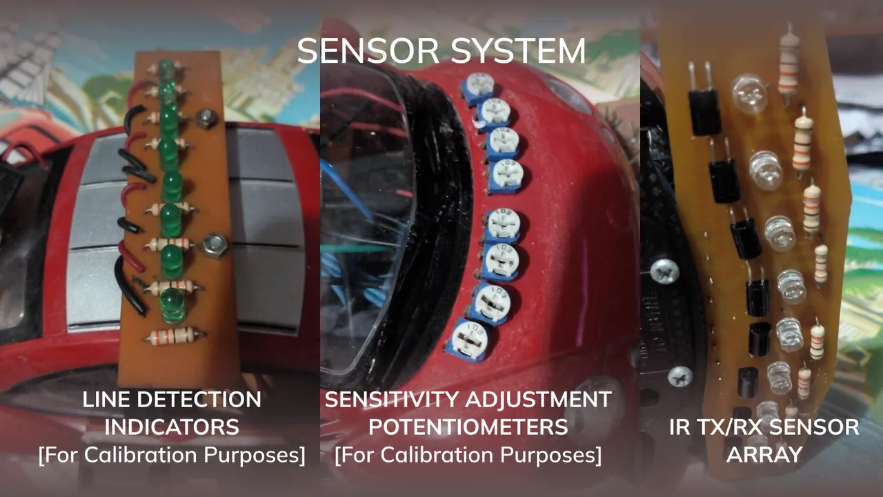
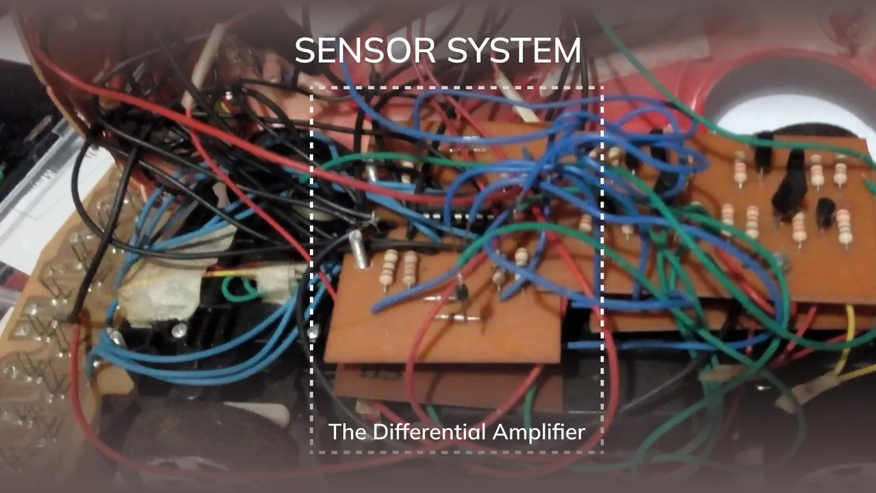
The output of the IR receiver is being fed into a differential amplifier. The sensitivity of the sensor is controlled by a potentiometer. This also useful in calibrating the sensors to deal with different environments.
I made eight pairs of this sensors. The two or four pair of sensors in the middle be used to monitor if the robot is in line with the track. The outer sensors will function to determine in which direction the robot should steer to when it is out of the line.
The Batteries
One of the challenges in making this project is the space for the batteries. I planned on using AA batteries as it is what I have readily available at that time.
The Logic Unit
This is the part that I wanted my student to design himself using logic gates. Unfortunately, due to unforeseen events, my student, although he is very interested to continue, was not able to do so.
I did not try to finish the project hoping that my student will one day return and continue the project. Years passed and I also forgot about the project until I came across the STEM community.
There it is, that is the story of the unfinished line follower that I’ve kept for so long. 😁
Thank you for taking the time to read my post.
This is my very post on the STEM community so I am very interested on your thoughts.
Simple automation using Arduino was once one of my previous side hustles. I've been helping a lot college students in making their electronic projects/thesis using Arduino
Again, thank you and more power!
HIVE On!