Cordial greetings to all my beloved readers... in order to complement our previous learning today we are going to implement communication between two microcontrollers using the RS485 protocol in HALF DUPLEX mode.
We will describe the use of the MAX487 protocol adapter (converter) as an alternative to MAX485 and we will simulate an application in which a server microcontroller receives the state of a level variable from a remote tank sent by a client microcontroller, the server microcontroller will receive the state of the variable and will control 3 indicators, it can also send data to the client to control the power of a water pump that can maintain the level of the tank at a suitable value.
Cordial saludos a todos mis amados lectores... con la finalidad de complementar nuestro aprendizaje anterior hoy vamos a implementar comunicación entre dos microcontroladores usando el protocolo RS485 en modo HALF DUPLEX.
Describiremos el uso del adaptador de protocolo (conversor) MAX487 como alternativa del MAX485 y simularemos una aplicación en la que un microcontrolador servidor recibe el estado de una variable de nivel desde un tanque remoto enviada por un microcontrolador cliente, el microcontrolador servidor recibirá el estado de la variable y controlara 3 indicadores, además podrá enviarle datos al cliente para que controle la potencia de un bomba de agua que pueda mantener el nivel del tanque en un valor adecuado.

MAX487 |
|---|
In the libraries that I currently have for Proteus I do not have the MAX485 component that would be ideal to make this circuit, however the MAX487 can fulfill the role of replacement without any inconvenience, for this reason it will be the one that we will use in our simulated design.
It is an integrated circuit with 8 pins between which, in addition to the main power supply we will connect the TX and RX pins coming from our microcontroller for data exchange, an additional pin must be used to control the integrated in terms of its behavior as a transmitter and receiver (I will explain this a few paragraphs later). Next let's see some technical data about this chip.
En las librerías que poseo actualmente para Proteus no dispongo del componente MAX485 que sería el ideal para hacer este circuito, sin embargo el MAX487 puede cumplir el papel de reemplazo sin ningún inconveniente, por esta razón será el que usaremos en nuestro diseño simulado.
Se trata de un circuito integrado con 8 Pines entre los cuales, además de la alimentación principal vamos a conectar los pines TX y RX provenientes de nuestro microcontrolador para el intercambio de datos, un Pin adicional debe ser usado para controlar el integrado en cuanto a su comportamiento como transmisor y receptor (esto lo explicare unos párrafos más adelante). A continuación veamos algunos datos técnicos sobre este integrado.


alldatasheet
The transmission lines between two distant devices are the A and B located on pins 6 and 7, pins 5 and 8 are for the power supply of the integrated (5 VDC), pins 2 and 3 (RE and DE) are used to control by the state of a bit when a data will be sent and when it will be received so this state must be opposite between two devices communicating in half duplex (one transmits and the other receives).
And pins 1 and 4 (RO and DI) are the ones that connect to the RX and TX pins of the microcontroller for data exchange. We will use the USART protocol in the microcontroller as we did in the past, the difference is that through the MAX487 integrated we will be able to establish communications over much longer distances, with higher speed and high fidelity due to the performance of the RS485 protocol.
Las líneas de transmisión entre dos dispositivos distantes son las A y B ubicadas en los pines 6 y 7, los pines 5 y 8 son para la alimentación del integrado (5 VDC), los pines 2 y 3 (RE y DE) se utilizan para controlar mediante el estado de un bit cuando se enviará un dato y cuando se recibirá por lo que este estado debe ser opuesto entre dos dispositivos que se comunican en half duplex (uno transmite y el otro recibe).
Y los pines 1 y 4 (RO y DI) son los que se conectan a los pines RX y TX del microcontrolador para el intercambio de datos. Usaremos el protocolo USART en el microcontrolador como lo hicimos en el pasado, la diferencia es que mediante el integrado MAX487 podremos establecer comunicaciones a distancias mucho más largas, con mayor velocidad y una alta fidelidad debido a las prestaciones del protocolo RS485.

Physical connections between devices
As you can see, each MAX487 chip must have a pull-up resistor and a pull-down resistor connected to pins A and B in order to function properly. Although I have placed each chip very close to each other, it is assumed that they can be hundreds of meters apart (which is one of the main advantages of transmitting serial data via RS485).
Como se puede notar cada chip MAX487 debe tener una resistencia en pull-up y otra en pull-down conectada en sus pines A y B para que puedan funcionar correctamente. Aunque he puesto muy cerca cada integrado se supone que estos pueden estar a cientos de metros de distancia (que es una de las principales ventajas por la que transmitimos datos seriales mediante RS485).
Application example |
|---|
We have a tank to store any liquid in an industrial process, this tank has a level sensor (which we will simulate with a potentiometer) and a water pump located near the tank that can be regulated by PWM signal.
In a control room 400 meters away is an operator who has the task of keeping the tank within a suitable level, has three lights that can indicate if the level is below the allowable value (LOW), above the allowable value (HIGH) or within the allowable range (GOOD), also has a potentiometer through which you can control the power of the pump (which is 400 meters away) to stop or increase the flow of liquid to the tank as required.
Tenemos un tanque para almacenar cualquier líquido en un proceso industrial, este tanque cuenta con un sensor de nivel (que simularemos con un potenciómetro) y una bomba de agua ubicada cerca del tanque que se puede regular mediante señal PWM.
En una sala de control a 400 metros de distancia se encuentra un operador que tiene la tarea de mantener el tanque dentro de un nivel adecuado, dispone de tres luces que pueden indicarle si el nivel está por debajo del valor permisible (LOW), por encima del valor permisible (HIGH) o dentro del rango permitido (GOOD), además dispone de un potenciómetro mediante el cual puede controlar la potencia de la bomba (que está a 400 metros de distancia) para detener o aumentar el flujo del líquido al tanque segun se requiera.

Roihuvuori watertower2. Author: Юкатан.,
Source: Wikimedia, license: This file is licensed under the Creative Commons Attribution-Share Alike 4.0 International

Operador de Itaipu Binacional jogando xadrez 😅. Author: Lechatjaune, Source Wikimedia, License: This file is licensed under the Creative Commons Attribution-Share Alike 4.0 International
Task Assignments |
|---|
We will have a microcontroller in the field (client) that will be in charge of receiving and processing the data coming from the level sensor (Potentiometer), it will transmit this data to the control room and will receive the instructions from the control room to set the pump power, i.e., it is this microcontroller that will generate the PWM signal to control the pump power but the value to set PWM will come from the control room.
Tendremos un microcontrolador en campo (cliente) que se encargará de recibir y procesar los datos provenientes del sensor de nivel (Potenciómetro), transmitirá estos datos hasta sala de control y recibirá las instrucciones desde sala de control para establecer la potencia de la bomba, es decir, es este microcontrolador quien va a generar la señal PWM para controlar la potencia de la bomba pero el valor en que establecerá PWM vendrá desde sala de control.
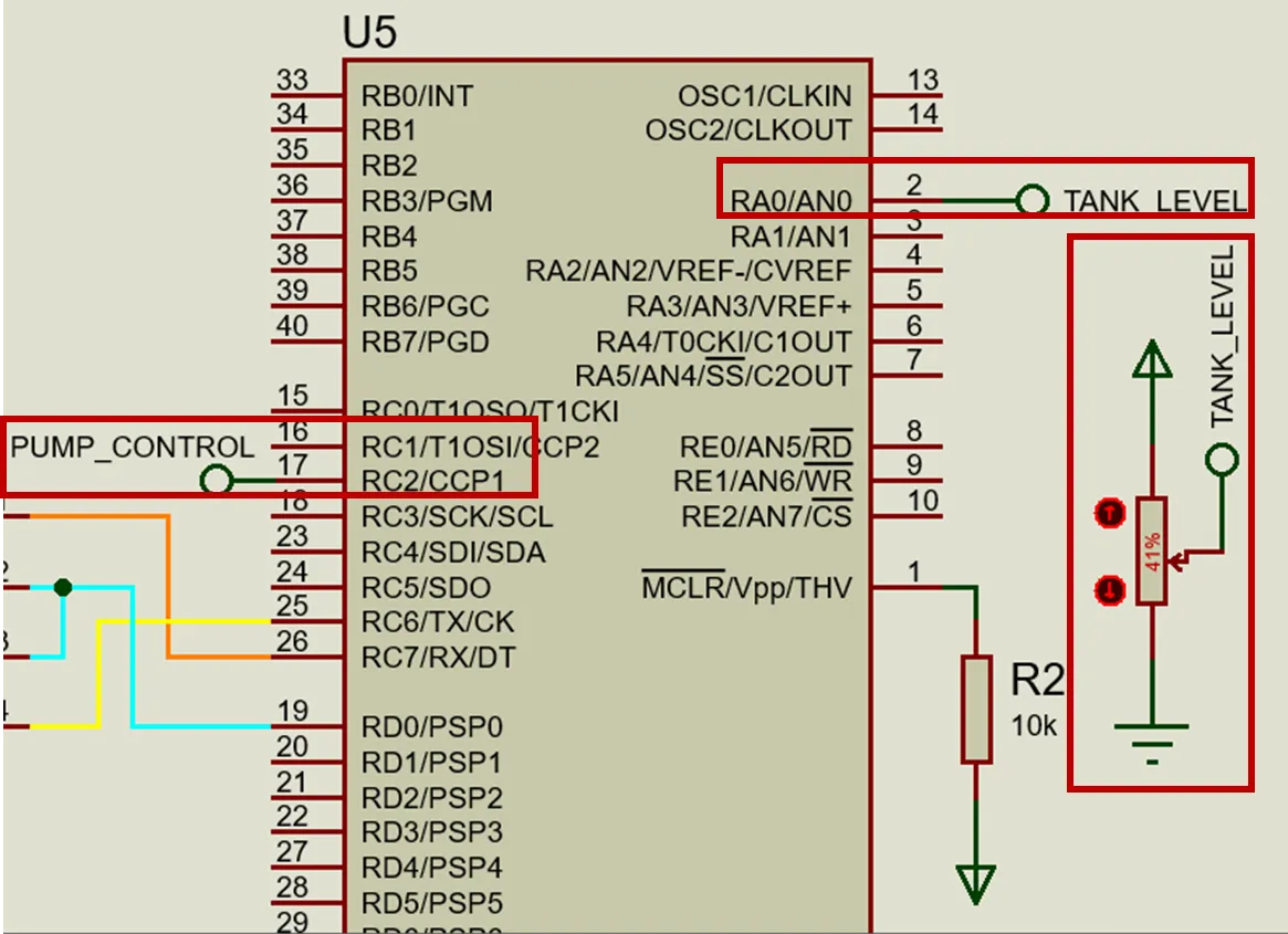
Client microcontroller details src: @electronico
We will have a microcontroller in the control room (Server), it will receive the level status from the client microcontroller and depending on the status it will turn on an indicator light so that the operator can take actions in the process.
This microcontroller will have connected a potentiometer in one of its ADC channels so that the operator can control the power of the pump, it will receive the signals from the ADC and transmit them to the client microcontroller to adjust its PWM output.
Tendremos un microcontrolador en sala de control (Servidor), este recibirá el estado del nivel desde el microcontrolador cliente y segun sea el estado encenderá una luz indicativa para que el operador pueda tomar acciones en el proceso.
Este microcontrolador tendrá conectado un Potenciómetro en uno de sus canales ADC para que el operador pueda controlar la potencia de la bomba, recibirá las señales del ADC y las transmitirá al microcontrolador cliente para que ajuste su salida en PWM.

Server microcontroller details src: @electronico
We could have set everything up automatically, i.e., have the server microcontroller send the client microcontroller the PWM values for pump power control based on the level data received from the client microcontroller without operator intervention, but then the operator would just be playing chess so we have also assigned him a task within the 😅 process.
Pudimos haber establecido todo de forma automática, es decir, que el microcontrolador servidor envíe al microcontrolador cliente los valores de PWM para control de potencia de la bomba basados en los datos de nivel recibidos desde el microcontrolador cliente sin intervención del operador, pero entonces el operador solo se dedicaría a jugar ajedrez así que también le hemos asignado una tarea dentro del proceso 😅.
Programming the server microcontroller |
|---|
For the purposes of the microcontroller we continue using the USART protocol, therefore all the knowledge we have acquired previously is valid for the realization of the program. We start with the configuration lines.
Para efectos del microcontrolador seguimos usando el protocolo USART por lo tanto son válidos todos los conocimientos que hemos adquirido anteriormente para la realización del programa. Iniciamos con las líneas de configuración.
#include <16f877a.h>

#device ADC = 10

#device PASS_STRINGS = IN_RAM

#fuses HS,NOWDT,NOPROTECT,NOPUT,NOLVP,BROWNOUT

#use delay(clock=20M)

#use RS232(BAUD=9600, BITS=8, PARITY=N, XMIT=PIN_C6, RCV=PIN_C7)

#use standard_io(D)

#define RS_MODE PIN_D0

#define HIGH_LEVEL PIN_D1

#define LOW_LEVEL PIN_D2

#define GOOD_LEVEL PIN_D3

#include <get_string.c

#include <map_function.c

#include <stdlib.h
Now we must consider that our microcontroller will have two types of behaviors (transmitter or receiver), never simultaneously because we are in HALF DUPLEX, so in our program we must write the behavior it will have when it is receiving data and the one it will have when it is transmitting, we must also set a Pin to control the MAX487 and switch between operating as Transmitter or Receiver, for this purpose we will create a variable called bit, we also create the variable string to handle the incoming data.
When bit is 1 it will be transmitted, in this case we query the ADC value and convert its 10bit value (0 to 1023) to an 8bit equivalent (0 to 255), we will store the result in the variable pwm_value and transmit it to the client microcontroller to adjust its PWM output to that value (pump power control).
Ahora debemos considerar que nuestro microcontrolador tendrá dos tipos de comportamientos (transmisor o receptor), nunca de forma simultánea porque estamos en HALF DUPLEX, así que en nuestro programa deberemos escribir el comportamiento que tendrá cuando esté recibiendo datos y el que tendrá cuando esté transmitiendo, además deberemos establecer un Pin para controlar el MAX487 y conmutar entre funcionar como Transmisor o Receptor, para este propósito crearemos una variable llamada bit, también creamos la variable string para manejar los datos entrantes.
Cuando bit sea 1 se transmitirá, en este caso consultamos el valor del ADC y convertimos su valor de 10bits (0 a 1023) en un equivalente a 8bits (0 a 255), guardaremos el resultado en la variable pwm_value y se la transmitiremos al microcontrolador cliente para que ajuste su salida PWM a ese valor (control de potencia de la bomba).
int bit = 1;

char string[10];

void main()

{

   output_low(RS_MODE);

   setup_adc_ports(AN0);

   setup_adc(adc_clock_internal);

   while(true)

   {

      while(bit == 1)

      {

         output_high(RS_MODE);

         set_adc_channel(0);

         long adc_value = read_adc();

         int pwm_value = map(adc_value, 0, 1023, 0, 255);

         printf("%u\r\n", pwm_value);

         delay_ms(10);

         bit = 0;

      }
The reason why we set bit = 0; at the end of the line is to get out of the while loop or rather, out of transmit mode and into receive mode, this is done constantly to monitor the state of the level and send the PWM value continuously. RS_MODE which represents the PIN_D0 is toggled from one state to another to switch between transmitter mode and receiver mode.
When we switch to receiver mode we check the value being received from the client microcontroller ADC which is a representation of the tank level, we convert the data type to long with atol(string) and then evaluate the data using if conditionals considering a value below 400 as low level and above 800 as high level. When the value is between these two it will be considered a good level and in each case an indicator LED is activated.
La razón por la que establecemos bit = 0; al final de la línea es para salir del bucle while o mejor dicho, del modo transmitir y pasar al modo recibir, esto se hace constantemente para monitorear el estado del nivel y enviar el valor de PWM de forma continua. RS_MODE que representa el PIN_D0 se conmuta de un estado a otro para cambiar entre modo transmisor y modo receptor.
Cuando pasamos al modo receptor verificamos el valor que se está recibiendo del ADC del microcontrolador cliente el cual es una representación del nivel del tanque, convertimos el tipo de dato a long con atol(string) y luego evaluamos el dato mediante condicionales if considerando un valor inferior a 400 como bajo nivel y sobre 800 como alto nivel. Cuando el valor esta entre estos dos se considerara un buen nivel y en cada caso se activa un LED indicador.
      output_low(RS_MODE);

      read_string(string, 10);

      if(strlen(string) > 0)

      {

         delay_ms(10);

         long incoming_value = atol(string);

         output_d(0x00);

         if(incoming_value >  800)

         {

            output_high(HIGH_LEVEL);

         }

         else if(incoming_value >  400)

         {

         output_high(LOW_LEVEL);

         }

         else

         {

         output_high(GOOD_LEVEL);

         }

         bit = 1;

      }

   }

}
It is important to note that at the end we set bit = 1 again; to go back to transmission mode.
Es importante resaltar que al final volvemos a colocar bit = 1; para pasar de nuevo al modo transmisión.
Programming the client microcontroller |
|---|
Initially the configuration lines are similar to those of the server microcontroller, but this microcontroller must generate PWM to control the power of the pump, this makes necessary the configuration of the CCP module to generate PWM, in addition we will configure the ADC to receive the simulated level variable by means of the potentiometer.
Inicialmente las líneas de configuración son similares a las del microcontrolador servidor, pero este microcontrolador debe generar PWM para controlar la potencia de la bomba, esto hace que sea necesario la configuración del módulo CCP para generar PWM, además configuraremos el ADC para recibir la variable de nivel simulada mediante el potenciómetro.
#include <16f877a.h>

#device ADC = 10

#device PASS_STRINGS = IN_RAM

#fuses HS,NOWDT,NOPROTECT,NOPUT,NOLVP,BROWNOUT

#use delay(clock=20M)

#use RS232(BAUD=9600, BITS=8, PARITY=N, XMIT=PIN_C6, RCV=PIN_C7)

#use standard_io(D)

#define RS_MODE PIN_D0

#include <get_string.c

#include <stdlib.h

char string[10];

int bit = 1;

void main()

{

   output_low(RS_MODE);

   setup_adc_ports(AN0);

   setup_adc(adc_clock_internal);

   setup_timer_2(t2_div_by_16, 255, 1);

   setup_ccp1(ccp_pwm);

   set_pwm1_duty(0);
If the microcontroller starts as transmitter the client must do it as receiver, this is what we do by setting bit = 1 in this case set output_low(RS_MODE), this is setting the D_0 bit of the client microcontroller to 0 setting it as receiver, in that case we query if a data has been received and we adapt it to set the PWM output based on the received data.
Si el microcontrolador inicia como transmisor el cliente debe hacerlo como receptor, es lo que hacemos fijando bit = 1 en este caso establece output_low(RS_MODE), esto es poner el bit del D_0 del microcontrolador cliente a 0 estableciéndose como receptor, en ese caso consultamos si se ha recibido un dato y lo adaptamos para establecer la salida de PWM con base en el dato recibido.
   while(true)

   {

      while(bit == 1)

      {

         output_low(RS_MODE);

         if(kbhit() > 0)

         {

            read_string(string, 10);

            int pwm_value = atoi(string);

            set_pwm1_duty(pwm_value);

            delay_ms(10);

            bit = 0;

         }

      }
At the end we set bit = 0; to go to transmission mode, in this mode what we do is to read the value being received by the ADC channel which represents the liquid level of the tank and this data is transmitted to be received by the server microcontroller. Finally bit = 1 is set; and the cycle repeats.
Al final fijamos bit = 0; para pasar a modo transmisión, en este modo lo que hacemos es leer el valor que se está recibiendo por el canal del ADC el cual representa el nivel de líquido que tiene el tanque y este dato se transmite para que sea recibido por el microcontrolador servidor. Finalmente se establece bit = 1; y el ciclo se repite.
      output_high(RS_MODE);

      delay_ms(1);

     set_adc_channel(0);

      long adc_value = read_adc();

      printf("%Lu\r\n", adc_value);

      delay_ms(1);

     bit = 1;

   }

}
Simulation |
|---|
We already have everything ready to run the simulation, what will be done in the simulation will be to vary the potentiometer that simulates the level of the tank, the client microcontroller must transmit this value to the server microcontroller, we will know if the data is being received because the leds will light up for high, medium and low values (each one for a range of values), if it happens it means that the client is transmitting correctly to the server.
Once verified the previous thing we are going to vary the potentiometer connected to the server which controls the PWM output of the client, we will evaluate this output with the oscilloscope and if when varying the potentiometer the PWM signal varies it means that the server is transmitting correctly towards the client.
If both cases are successful we will have created a remote level control (up to 1200 meters away) to control the level of a tank. Let's find out if we succeed!
Ya tenemos todo listo para correr la simulación, lo que se hará en la simulación será variar el potenciómetro que simula el nivel del tanque, el microcontrolador cliente deberá transmitir este valor al microcontrolador servidor, sabremos si se están recibiendo los datos porque los leds se encenderán para valores altos, medios y bajos (cada uno para un rango de valores), si ocurre significa que el cliente está transmitiendo de forma correcta hasta el servidor.
Una vez verificado lo anterior vamos a variar el potenciómetro conectado al servidor el cual controla la salida PWM del cliente, evaluaremos dicha salida con el osciloscopio y si al variar el potenciómetro varía la señal PWM significa que el servidor está transmitiendo correctamente hacia el cliente.
Si ambos casos se producen con éxito habremos creado un control de nivel remoto (de hasta 1200 metros de distancia) para controlar el nivel de un tanque. Vamos a descubrir si lo logramos!!