This is the second article in a series that I have entitled "Control and monitoring" and that will probably consist of 4 articles that will complement each other in order to understand a complex control and monitoring system using closed-loop control techniques.
It is important to have read the previous article for a better understanding of the present one as well as certain articles that I will cite throughout the series and that have been published in the past.
Once we understand the philosophy of control in a closed-loop system and represent it in the control of a valve, we can go back to that idea that visited me when I was about to go to sleep to steal a few extra hours while I was enthusiastically thinking about how to make it possible.
Could I write an article simulating that process for controlling and monitoring a valve? The main problem came because in our electronic simulators like Proteus we do not have a pneumatically actuated valve.
But the signals involved in the process are electrical, remember? 1 for execution and 2 for monitoring so I just had to think of a circuit that is able to handle these 3 signals and behave as a pneumatic valve would.
Este es el segundo artículo de una serie que he titulado "Control and monitoring" y que probablemente conste de 4 artículos que se complementarán entre sí para poder entender un sistema complejo de control y monitoreo usando técnicas de control a lazo cerrado.
Es importante haber leído el artículo anterior para una mejor comprensión del presente al igual que ciertos artículos que citaré a lo largo de la serie y que han sido publicados en el pasado.
Una vez que ya comprendimos la filosofía de control en un sistema a lazo cerrado y lo representamos en el control de una válvula podemos volver a aquella idea que me visitó cuando estaba a punto de dormir para robarme unas horas extra mientras pensaba con entusiasmo la forma de hacerlo posible.
¿Podría escribir un artículo en el que simulace aquel proceso para el control y monitoreo de una válvula? el problema principal venía porque en nuestros simuladores electrónicos como Proteus no disponemos de una válvula de accionamiento neumático.
Pero las señales que intervienen en el proceso son eléctricas ¿recuerdas? 1 de ejecución y 2 de monitoreo así que solo tenía que pensar en un circuito que sea capaz de manejar estas 3 señales y comportarse como lo haría una válvula neumática.
Yes, that thing you just saw was what I designed in the workshop of my mind to carry out the desired task, if it scared you a little don't worry, we will understand it very easy with the cake theory (I don't even know if that exists as a theory 😅).
What the theoretical theory says (if it doesn't exist as of this moment I give it existence) is that if you are asked to eat a whole cake you will doubt that you can do it if you think about eating it all at once, however, if it is chopped in pieces and given to you in parts you will eat the whole cake without even noticing it.
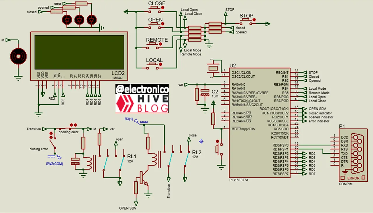
Now we are going to cut our cake, we will start with the most important piece which are the connections, inputs and outputs that the microcontroller must handle.
Si, esa cosa que acabas de ver fue lo que diseñe en el taller de mi mente para que lleve a cabo la tarea deseada, si te ha asustado un poco no te preocupes, lo entenderemos muy fácil con la teoría del pastel (ni siquiera se si eso existe en forma de teoría 😅).
Lo que dice la teórica teoría (si no existe a partir de este momento le doy existencia) es que si se te pide comer un pastel entero dudarás en que puedes hacerlo si piensas en comerlo todo de una vez, sin embargo, si se pica en trozos y se te dan por partes comerás todo el pastel sin siquiera notarlo.
Ahora vamos a picar nuestro pastel, iniciaremos con el trozo más importante que son las conexiones, entradas y salidas que debe manejar el microcontrolador.

We have an analog input (ADC), when our SDV valve opens it lets gas through and this gas increases the variable pressure, that is, the opening of the valve will increase a variable, in the ADC we have a capacitor whose load through a resistor can simulate the variable by increasing the ADC in the opening signals and decreasing in the closing signals.
Then we have 7 discrete inputs that are named below with their respective function:
STOP: It is for a forced stop, when a high value is introduced by this input a stop of the whole process must be produced no matter in which phase it is, it has been placed in RB0 with the purpose of activating this interruption.
Closed: Receives the signal coming from the limiswitch that is activated when the valve is closed. The status of this input is used in conjunction with the status of the Opened input to determine the valve status.
Opened: Receives the signal from the limiswitch that is activated when the valve is open. The status of this input is used in conjunction with the status of the Closed input to determine the valve status.
Local Mode: A pulse on this input (sent from a pushbutton) activates the local mode which allows the process to be controlled from peripherals connected to the microcontroller and blocks remote control.
Remote Mode: A high pulse on this input activates the remote mode that allows the valve to be controlled from a PC by software, this mode blocks the local control.
Local Open: When the local mode is active a pushbutton can be used to place a high value on this input and open the valve (send open command).
Local Close: When local mode is active a pushbutton can be used to place a high value on this input and close the valve (stop sending open command).
In the following image we can see the pushbuttons with their pull-down resistors that are connected to these inputs.
Tenemos una entrada analógica (ADC), cuando nuestra válvula SDV abre deja pasar gas y este gas incrementa la variable presión, es decir, la apertura de la válvula incrementará una variable, en el ADC tenemos un capacitor cuya carga mediante una resistencia puede simular la variable incrementando el ADC en las señales de apertura y disminuyendo en las de cierre.
Luego tenemos 7 entradas discretas que se nombran a continuación con su respectiva función:
- STOP: Es para una parada forzada, cuando se introduce un valor alto por esta entrada se debe producir una parada de todo el proceso sin importar en qué fase este, se ha colocado en RB0 con la finalidad de activar dicha interrupción.
- Closed: Recibe la señal proveniente del limiswitch que se activa cuando la válvula está cerrada. El estado de esta entrada se usa en conjunto con el estado de la entrada Opened para determinar el estado de la válvula.
- Opened: Recibe la señal proveniente del limiswitch que se activa cuando la válvula está abierta. El estado de esta entrada se usa en conjunto con el estado de la entrada Closed para determinar el estado de la válvula.
- Local Mode: Un pulso en esta entrada (enviado desde un pulsador) activa el modo local que permite que se controle el proceso desde los periféricos conectados al microcontrolador y bloquea el control remoto.
- Remote Mode: Un pulso alto en esta entrada activa el modo remoto que permite controlar la válvula desde un PC por software, este modo bloquea el control local.
- Local Open: Cuando el modo local está activo se puede usar un pulsador para colocar un valor alto en esta entrada y abrir la válvula (enviar comando de apertura).
- Local Close: Cuando el modo local está activo se puede usar un pulsador para colocar un valor alto en esta entrada y cerrar la válvula (dejar de enviar comando de apertura).
En la siguiente imagen podemos ver los pulsadores con sus resistencias de pull-down que van conectados a estas entradas.

Regarding the outputs we could appreciate 4 discrete outputs in port C, the OPEN SDV output is the one used to send the open command, while this output is high the valve should be open and vice versa.
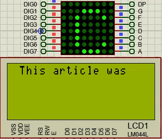
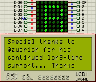
The outputs closed indicator, opened indicator and error indicator are to activate LED indicators corresponding to each valve status, these are combined with a 20x4 LCD display connected to Port D to provide local process information to an operator who wants to monitor in the area.
The engine is only there because it provoked me 😅 but its function is to decorate, of course, it will start when the OPEN SDV command is sent.
Respecto a las salidas pudimos apreciar 4 salidas discretas en el puerto C, la salida OPEN SDV es la que se usa para enviar el comando de apertura, mientras esta salida sea alta la válvula deberá estar abierta y viceversa.
Las salidas closed indicator, opened indicator y error indicator son para activar LEDs indicadores correspondientes a cada estado de la válvula, estos se combinan con una pantalla LCD 20x4 conectada en el Puerto D para ofrecer información local del proceso a un operador que desee monitorear en el área
El motor solo está ahí porque me provocó 😅 pero su función es adornar, claro, encenderá cuando se envié el comando OPEN SDV

Now we only have one piece of cake left, the circuit that will simulate the action of the valve, remember how an SDV valve would act.
If the open command is not present the valve will be closed and the limitswitch closed will be active.
When the open signal is sent the valve starts to open, the opening does not occur instantaneously but there is a transition process.
When the valve moves and the time it takes to fully open the limitswitches opened and closed will be inactive, their value will be 0 and this will be interpreted as valve in transition from closed to open. This state is temporary and only lasts a few seconds, otherwise it is interpreted as a fault.
When the valve is completely open the limitswitch opened sends signal 1 and the closed one sends signal 0. If this process is understood it is easy to deduce what happens when the open command (close signal) is deactivated.
In our circuit we use a transistor to receive the open signal and this signal will activate a relay, the contacts of this relay will be used as limitswich of closed because it will open when receiving the signal and in turn will send voltage to a second relay.
The second relay has a delay timer to simulate the transition and once active moves its contacts which simulates the opened limitswitch, in turn another contact sends voltage to the ADC to begin to increase.
Ahora solo nos queda un trozo de pastel, el circuito que simulará la acción de la válvula, recordemos cómo actuaría una válvula SDV.
Si no está presente el comando de apertura la válvula estará cerrada y el limitswitch closed estará activo.
Cuando se envía la señal de apertura la válvula comienza a abrirse, la apertura no ocurre de forma instantánea sino que hay un proceso de transición.
Cuando la válvula se mueve y el tiempo que tarde en abrirse completamente los limitswitchs opened y closed estarán inactivos, su valor será 0 y se interpretará esto como válvula en transición de cerrado a abierto. Este estado es temporal y solo dura unos pocos segundos, de lo contrario se interpreta que existe una falla.
Cuando la válvula está completamente abierta el limitswitch opened envía la señal 1 y el closed la señal 0. Si se entiende este proceso es fácil deducir lo que ocurre cuando se desactiva el comando de apertura (señal de cierre).
En nuestro circuito usamos un transistor para recibir la señal de apertura y esta señal activará un relé, los contactos de este relé se usarán como limitswich de closed porque se abrirá al recibir la señal y a su vez enviará tensión a un segundo relé.
El segundo relé tiene un temporizador de retardo para simular la transición y una vez activo mueve sus contactos en los cuales se simula el limiswitch de opened, a su vez otro contacto envía tensión al ADC para que comience a incrementar.

The opening error and closing error switches can be used to introduce errors in the process and check the behavior of the system to these errors.
Another thing that because it is obvious I did not mention is the serial port, since our design communicates with a PC is the reason why it is there.
In this way we already have designed the circuit for control and monitoring using a closed loop but it is still a body without a soul until we make the microcontroller program and everything comes to life.
Right now I am working on this program, I hope to have it ready for tomorrow, if it is the case I will try to publish it as soon as possible, for now we are left with the taste of the cake we have tasted, once again thank you for your company in this crazy adventure.
Los interruptores opening error y closing error pueden usarse para introducir errores en el proceso y comprobar el comportamiento del sistema ante estos errores.
Otra cosa que por ser obvia no mencioné es el puerto serial, ya que nuestro diseño se comunica con un PC es la razón de que esté ahí.
De esta forma ya tenemos diseñado el circuito para el control y monitoreo usando un lazo cerrado pero aún es un cuerpo sin alma hasta que hagamos el programa del microcontrolador y todo cobre vida.
Ahora mismo estoy trabajando en dicho programa, espero tenerlo listo para mañana, si es el caso intentaré publicarlo lo más rápido posible, por ahora nos quedamos con el sabor del pastel que hemos degustado, una vez más agradecido por tu compañía en esta loca aventura.