Recently I began rebuilding my music gear. I gave most of it away or sold it before moving south - it’d been so long I honestly thought I was probably done gigging. Then I played that gig in town at The Harp, and realized quickly that I need to get a sound rig back together.
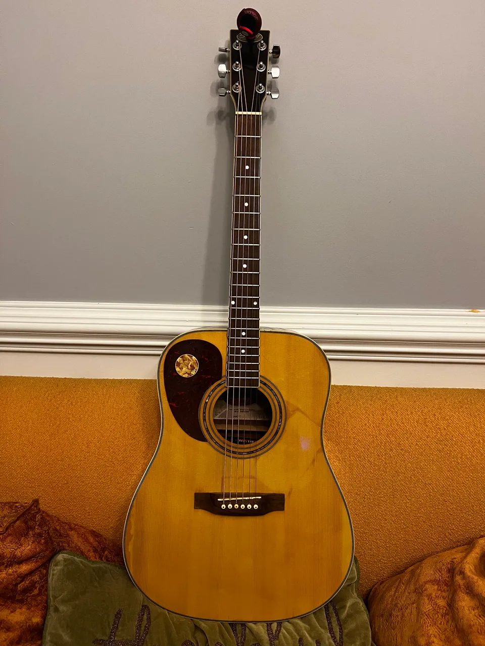
Before getting too hyped up about equipment, I needed to clean up my old guitar and see if the end result was something worth investing in building up as my stage instrument.
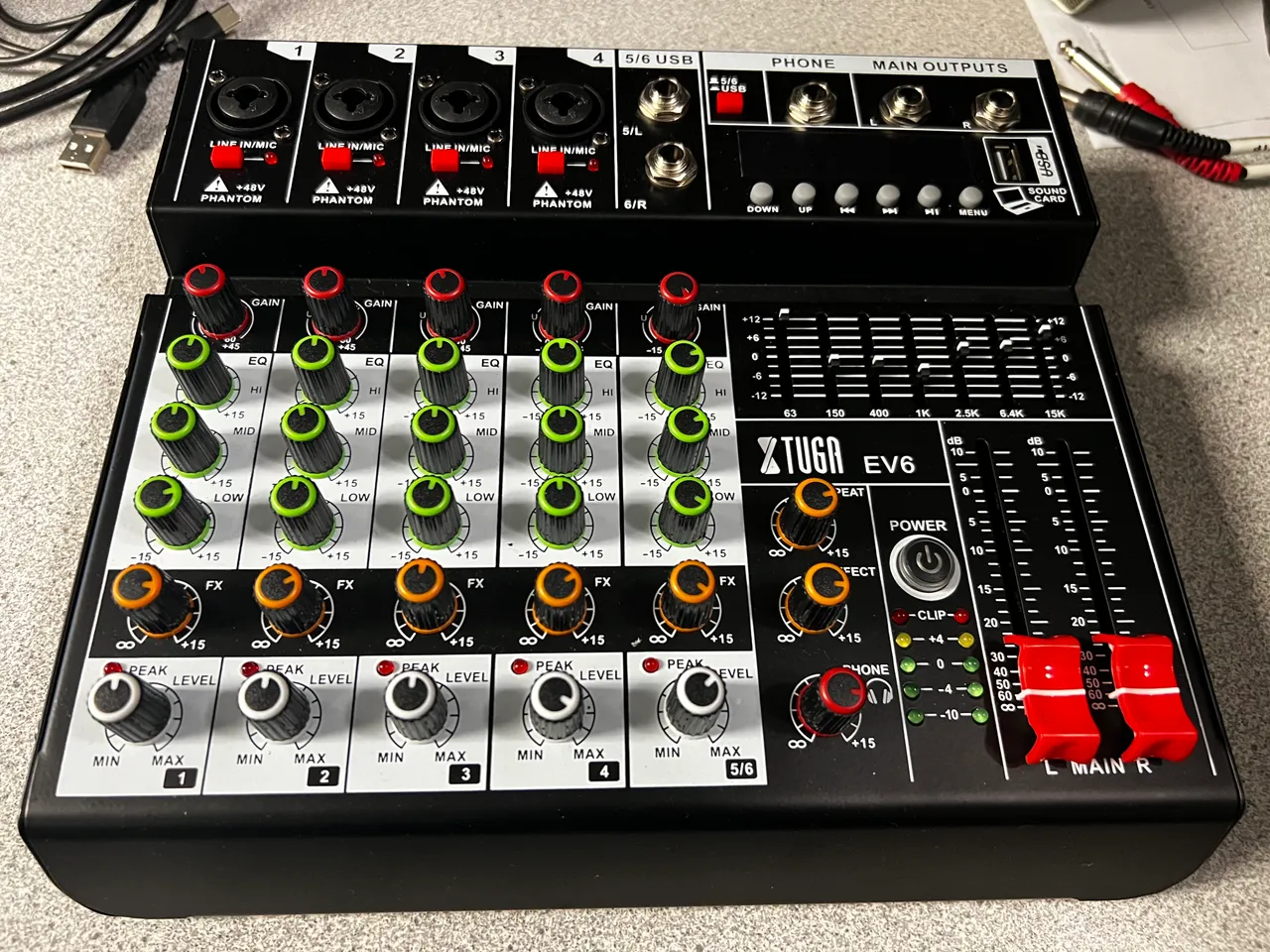
The Mixer
This was the first addition to my setup. I found it on marketplace for $40. Not much to say about it yet, except that I have it and from what I can tell, it works - which is good.

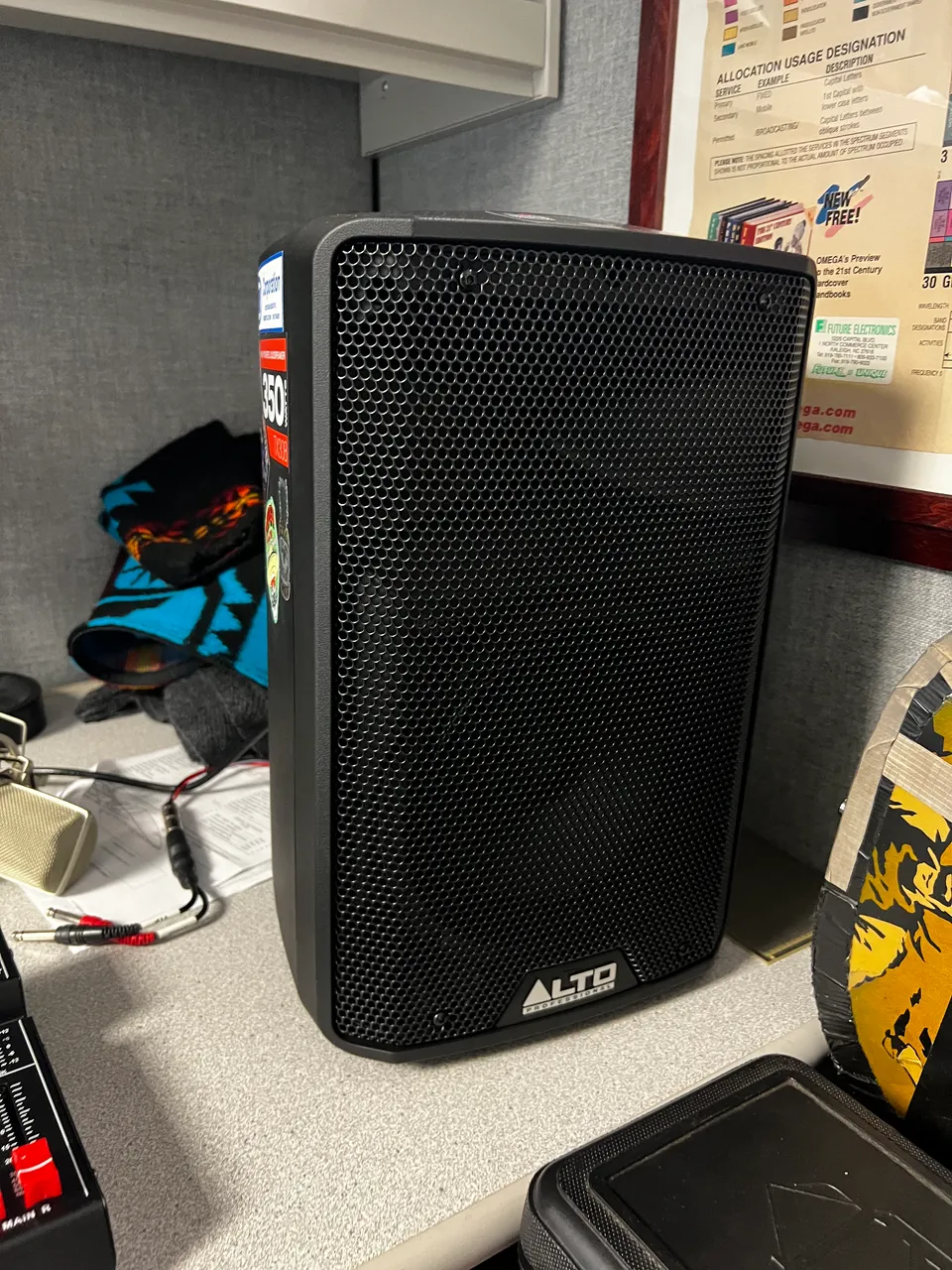
The Speaker
Another underwhelming part overall, but also very much necessary and hard to acquire cheaply. I had a lead on one that was about half the cost of the one I got - and three times the speaker wattage - but someone else snagged it up before I could get there.
I wound up with this instead. I don’t know much about it yet, but it looked nice so I promptly covered it with stickers.

This is a powered (or active) speaker. It has its own built in preamp, so I won’t need to lug around a big PA system. This was another deal, but not necessarily on sale - just a really fair priced option, I think maybe it was like $120, and at 350W, it should cover most bars and venues (I hope).

The Music Stand
This music stand is great. It was $30 on Amazon and it came with everything you see here, except the light. That was $6.00, but I remember how hard it was, site-reading in a dimly lit bar…a light would have improved the quality of my performance for sure.
The whole setup fits in this case, although typically it’s too difficult to zip it shut (I fought really hard to get this picture 🤣)

First time was the worst for assembling the stand. Now that I’ve done it, I look at this pile of pieces and can tell immediately what goes where…I can assemble the whole thing in less than a minute and that’s important to me. I really don’t like taking a long time to set up while people are sitting at the bar waiting for music.

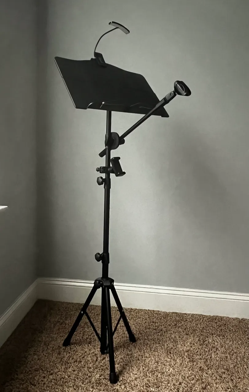
At the last performance (the test bed), I noticed it was a dim environment and it was very difficult to site-read. While most songs that got skipped got skipped because they weren’t suitable to be belted out over the crowd, some got passed over because it was too dark to make out the print. I added this light based on that experience, and hope it will prevent me from struggling to read in future performances.

The Microphone
I bought this microphone while I was overseas with the army, but couldn’t use it as the time because it requires phantom power. The new mixer has optional phantom power for all channels, so I’m hoping I may finally get to utilize this old thing.

Wiring the Stagg for Sound
…since I had to pull out the old mismatched pegs in the first place, I figured I might as well throw in some new ones that look a little nicer :)
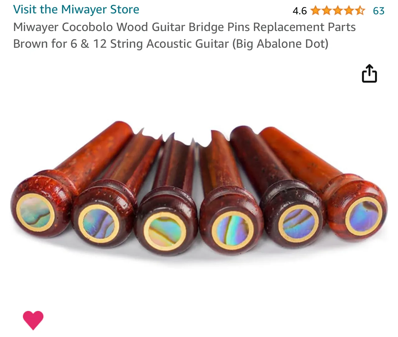
[source: Amazon.com]
Here is what the pegs looked like before. Not sure why I always have to be different, but this is a case where that didn’t work out so well.

I loosened the tuning heads and pulled the bridge pegs, but left the strings attached at the headstock to make restringing a little easier.

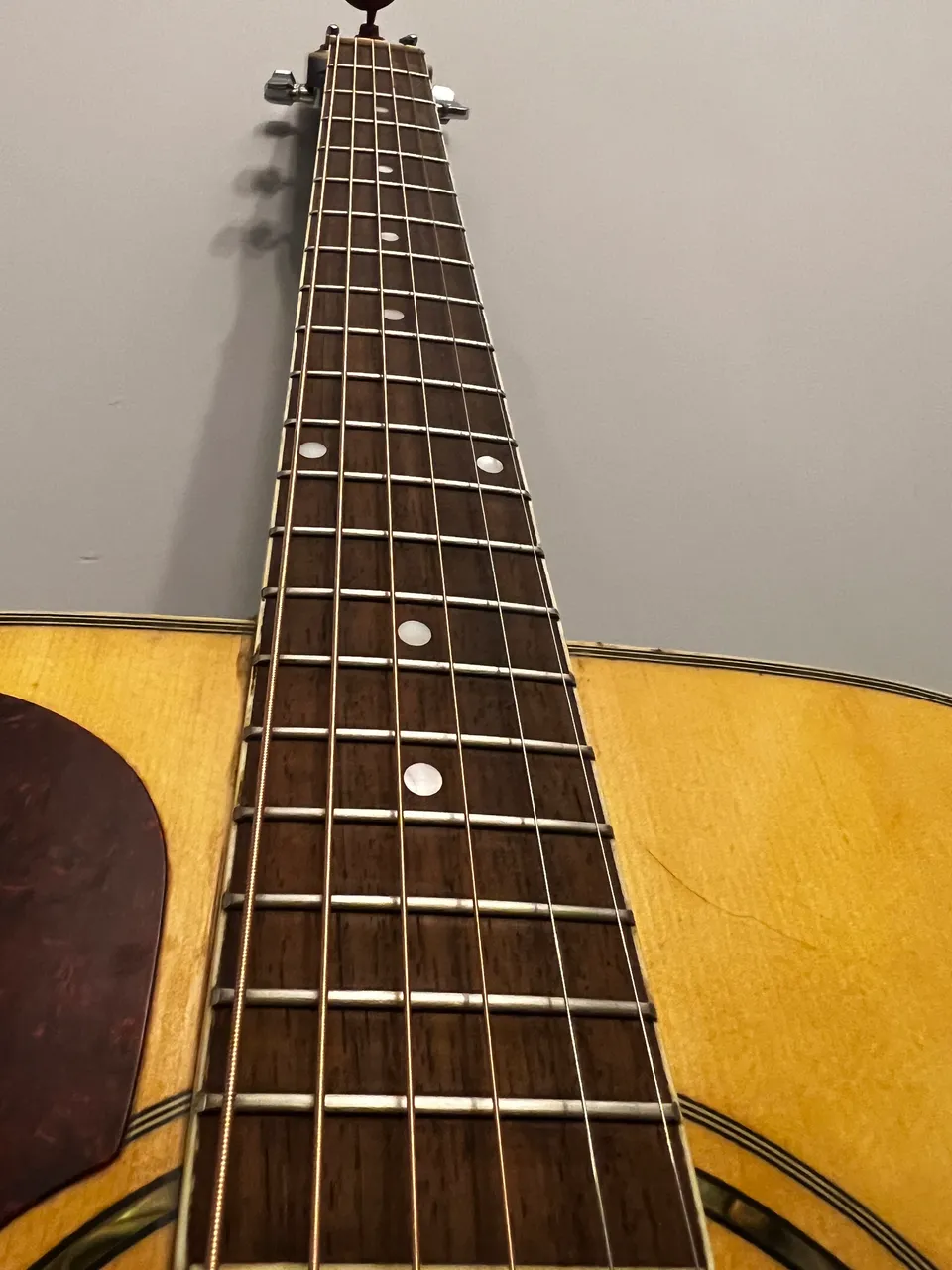
The fretboard on this guitar has probably never been cleaned, even after at least two owners and more than 12 years…and it shows!
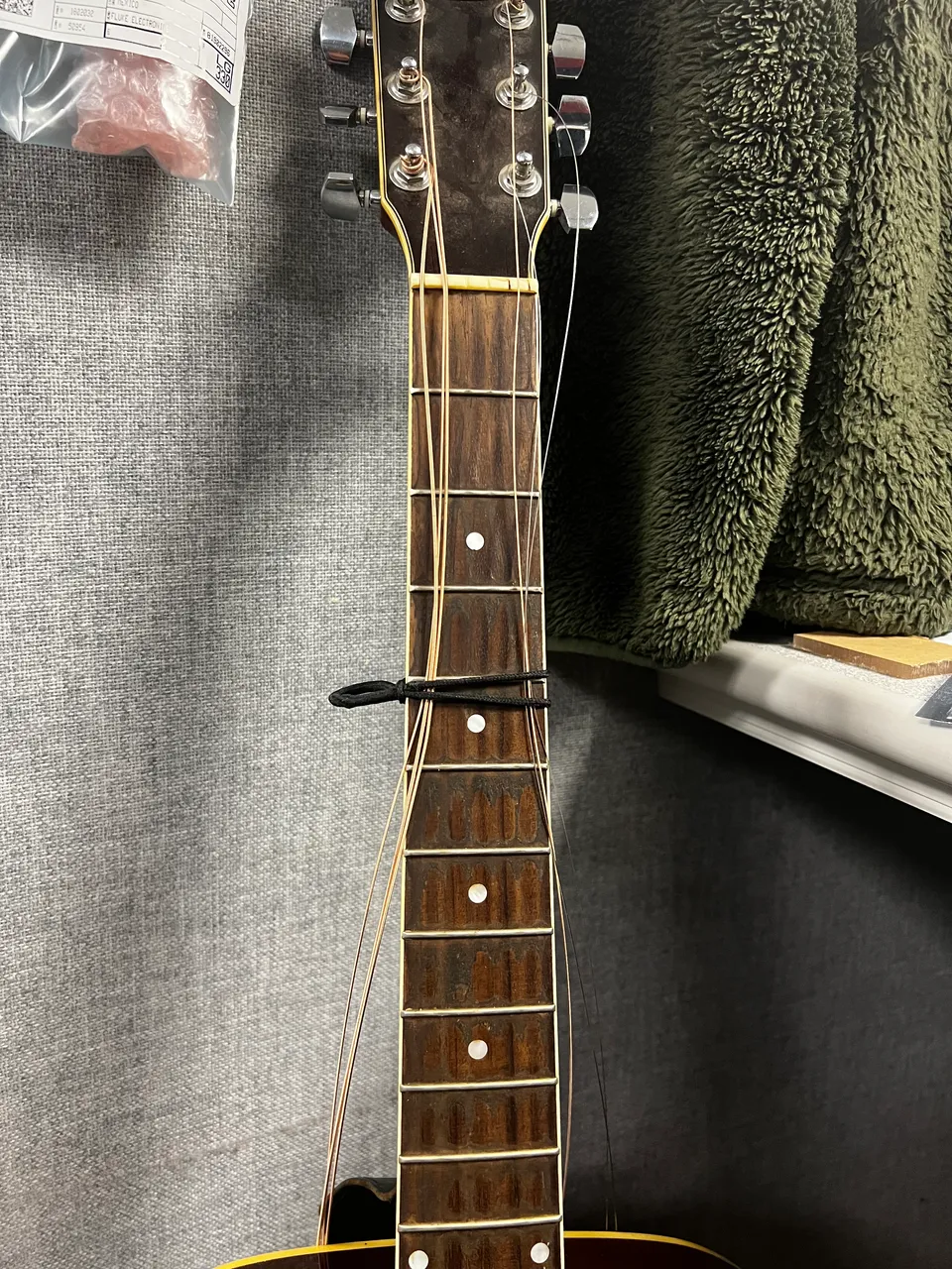


And real quick, since I already had the strings off, I went ahead and hit the fretboard with the Dremel (and a foam wheel) to clear off the decades of whatever the heck it is that builds up between the strings. Here it is, halfway done so you can see the difference.
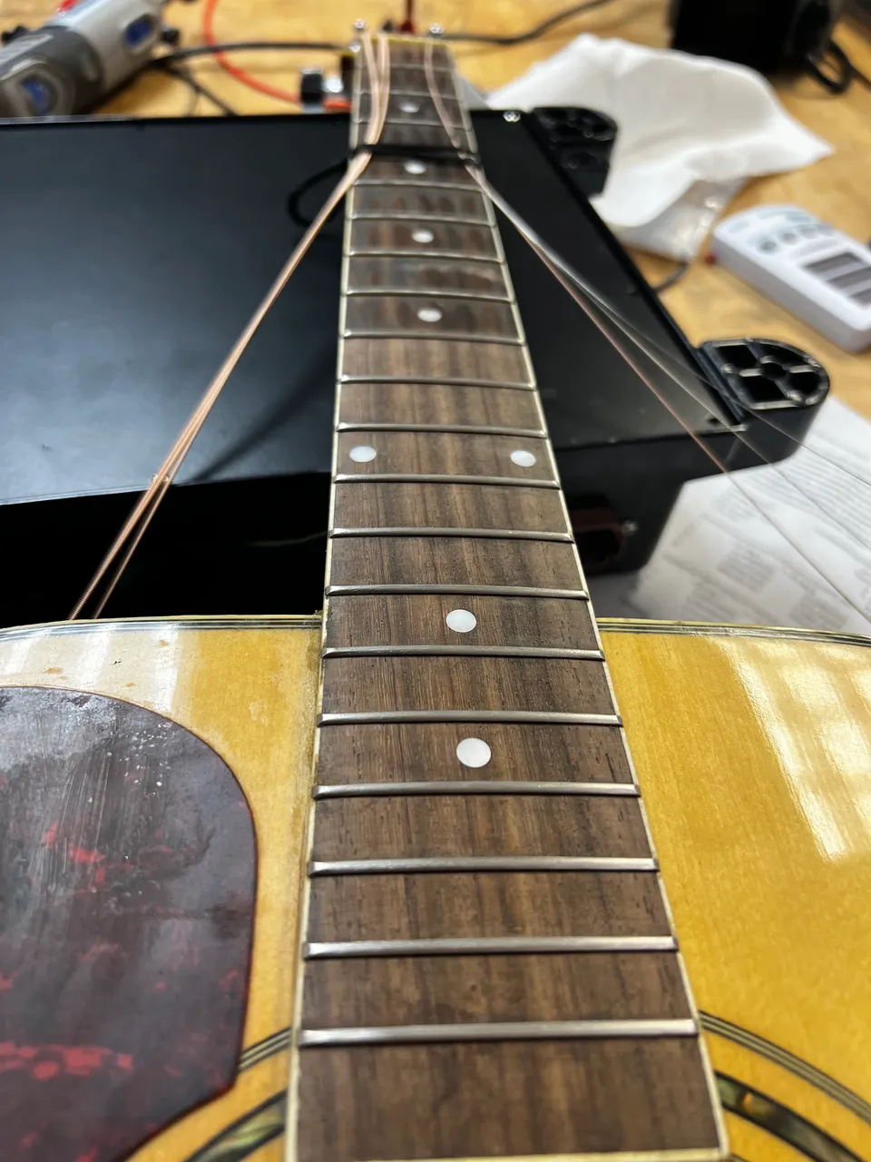
And here it is, all cleaned up.

Later I will wipe it down with some wood oil for the finishing touch.
…and now we’re off to the next thing! The parts are expected to arrive today, so the Stagg is laid out, opened up, and ready for surgery :)

…surgery which…did not go according to plan.
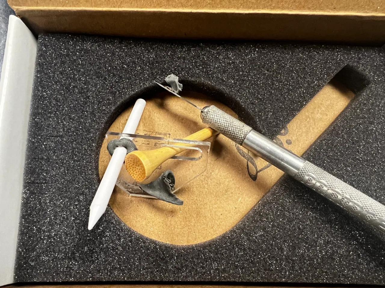
The pickup came with installation instructions, a jig and some golf tees for lining up with the saddle.

According to the instructions, the 3 piezos can be glued or taped, but taping results in an approximate 30% decrease in sound. I chose to go with glue.

You’re supposed to align the jig with the pins on the outside, then use sticky putty to hold the piezo to the jig, then put glue on the piezo, remove the whole jig from the face of the guitar, insert through the soundhole and use the pins to line the jig up from the inside and press/hold to dry.

The first one went deceivingly well. Then on the second one, the piezo pulled away from the putty and flipped upside down so while I was applying pressure to the jig I was actually gluing the piezo to the jig. Luckily I did a pull test too early and when it fell apart I saw that it was not connected properly. I scraped the whole thing off as well as I could (bye bye 30% 😖), and decided to go by hand from here, no jiggy bullshit.
For drilling a semi-big hole in thin panel wood like this, the step bit accomplishes the job with a lot less destruction than a refular drill bit.

I decided to put the input jack down in the area where it would be on an electric guitar. I recently added strap locks to both end, so I don’t want to replace my strap nut. I thought about putting it behind the strap nut - and that may have been better due to structural integrity - but I didn’t want the strap interfering with the connection and I dig that kinda grungy rock n roll style, so whatever, I did what I did.
For this step I just eyeballed a good spot and let her rip…pretty unceremonious honestly.

I removed the backshell from a half connector I cut while making the pedal board and used the now-thinner cable as a fish tape.
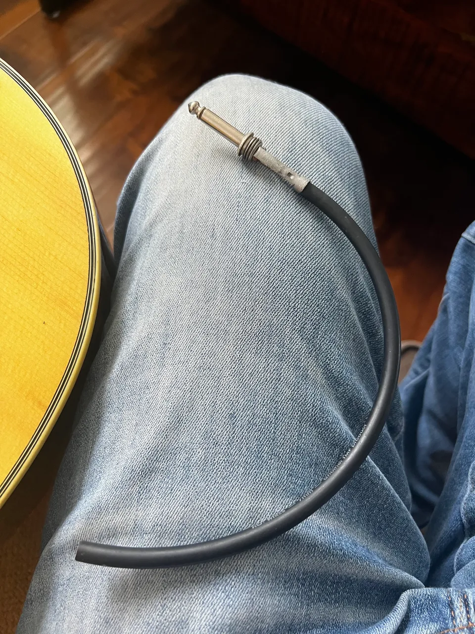
I couldn’t quite reach my arm far enough into the soundhole to push the connector through the body, so I pushed in the stripped through and connected the two with a single hand, holding the free end of the wore with the opposite hand. I had to push this through and separate them and pull it all back out a few times as I set the locknut position for the inside, but eventually, i liked it well enough to Loktite or whatever and crank it down.

Fretboard, all cleaned up:
And here it is, with everything except the pegs because i got impatient!
Making My Pedal Board
Finally, we’ll look at the most labor intensive part of the whole thing: building a pedal board.
I did some of the work before I decided it would be a cool project to share, but mostly I used an old scrap piece that was cutout from a plastic shelf as my base, and pretty much just started hooking stuff on. At the start, all I planned on having was a DI box for sound quality, a loop station, and a convenient way to power them with one power cord.

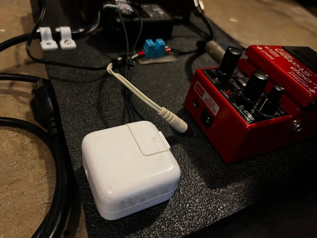
Because the mixer I found on Marketplace takes USB 5.0V, I added a decent USB brick to the panel. I soldered wires directly to the wall prongs, filled the recesses with glue, and folded them closed/into the wet glue. I did also first verify by continuity test that the prongs were still functional while folded in.
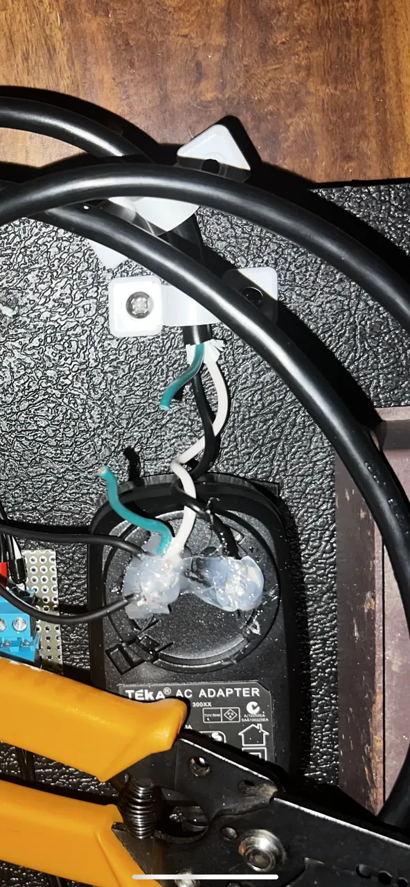
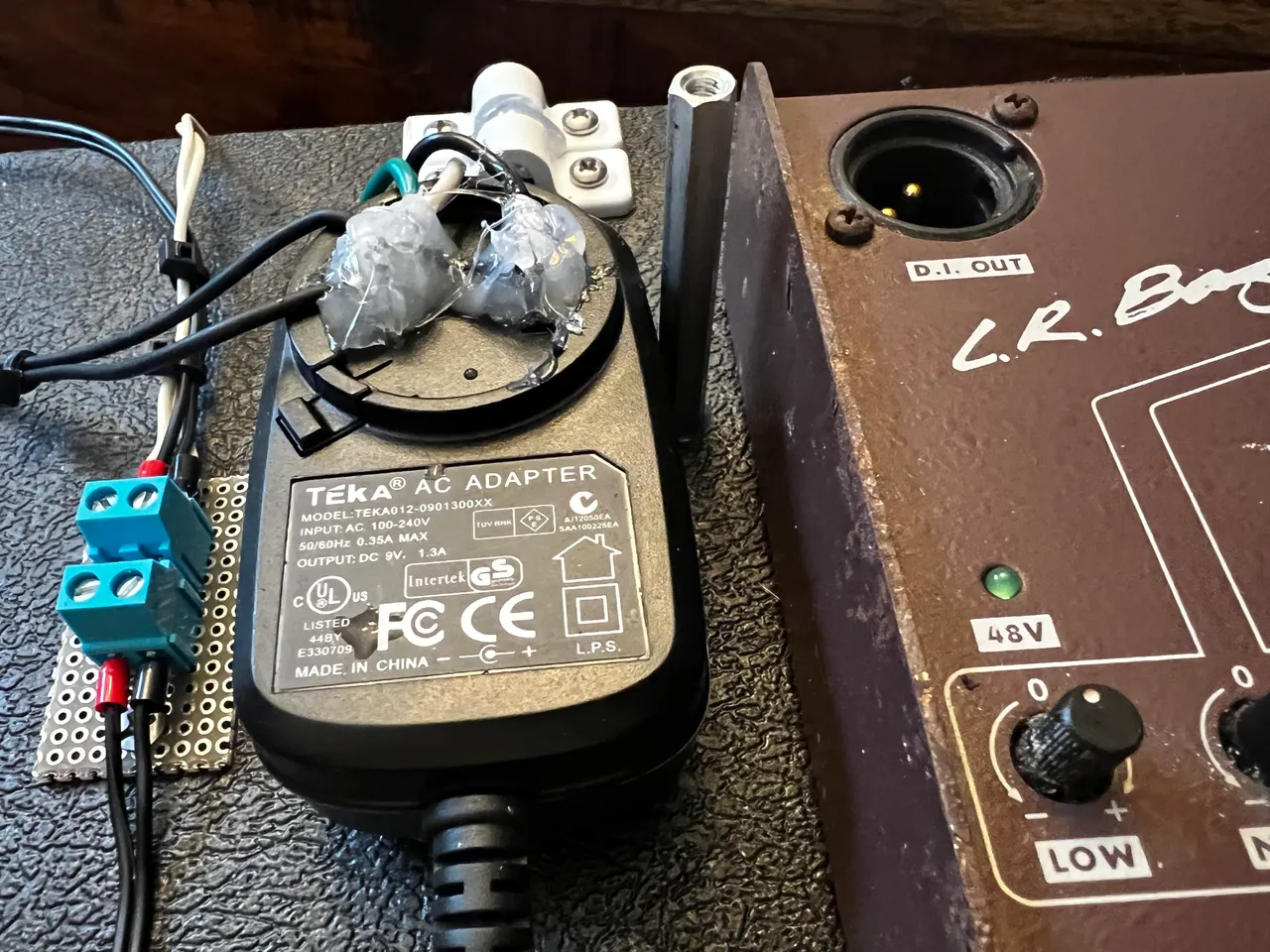
In order to cleanly draw 9V from one brick to two pedals without completely locking myself into soldered joints, I added a terminal connection between the wall wart and the DC connections. This way, if the block needs to be replaced I won’t have to cut my DC wires.

Even though I had plugged this into several other sources at this point, tonight when I plugged it in at home, it tripped the breaker. My first (and only) idea was to snip the ground wire I currently had running parallel to neutral. I reset the breaker, cut the ground wire and plugged it back in, and the power didn’t go out…ok, AC source is now verified…maybe I’ll put a ground plane on the base of the panel, but that’s gonna be pretty low on the list of shits I give.
I can connect to outlets wired in two different ways now without tripping a breaker, so it’s time to move on to the DC power issues.

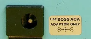
Depending on when it was made, BOSS pedals will have one of two DC connector styles.
| Column1 | Column2 |
|---|---|
 |  |
Here is a schematic excerpt I found online. It’s not for this pedal, but it is for a boss pedal with a PSA style DC connector (source identified below).

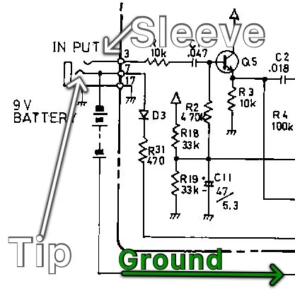
In the above image (source identified above on the unmarked version), I marked the tip and sleeve of the connector. In the expanded schematic, I noted that the trace coming off of the tip went to ground, and in the above excerpt you can see the sleeve connecting to a pullup…so the difference is almost certainly that the tip and sleeve are wired with opposite polarity. I can’t afford to replace anything if I destroy it so I hate to gamble, but, as it turns out, I may have done the real gambling when I connected it the first time.
After swapping the leads on one of the connectors, I connected the output and the power indicator came on…finally, good to go.
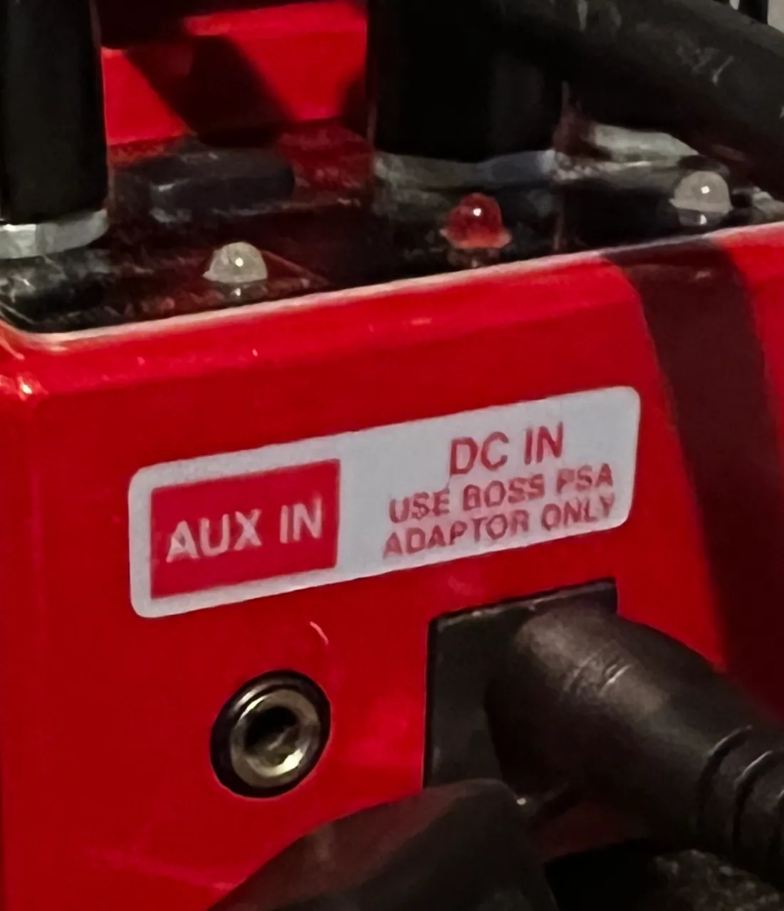
That’s mine, above. So mine’s a PSA type, and now in my mind I will assume PSA stands for Positive Sleeve Adapter.
Next: I hate relying on batteries. I don’t like disposing of them and potentially harming the environment, I don’t like buying new ones, and I really hate it when I find myself ready to jam, but having a dead battery and no replacement on-hand…all that stacks up to make a pretty solid case for a DC power supply in my mind, which is one reason I set out to create this board in the fist place (the other main reason is that it’s really a pain setting up and tearing down for a gig, so having a quick and easy solution (guitar in | sound out | single power connection) goes a long way.
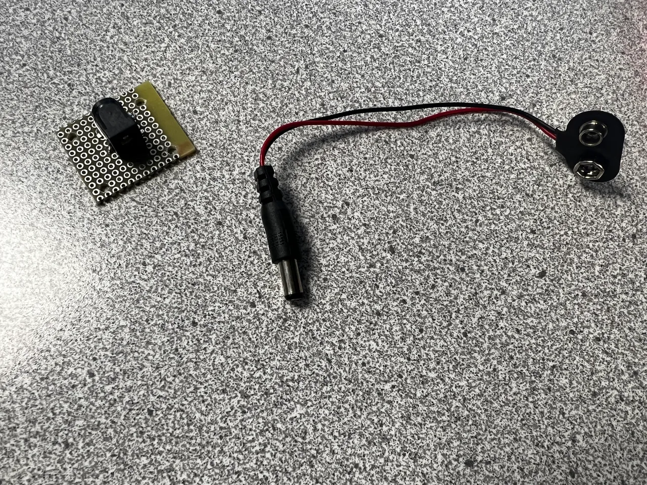
Anyway, I realized half way through my build, that my DI box doesn’t have a DC power input jack - but when I set out to do something, it gets done. So next I began preparing to add a DC power input jack to the DI box.
I bought this adapter from the site referenced as the image source. It was $0.99 and shipping was free…$1.07 after tax. The same thing was going for $6.00 on Amazon, so shop around if you’re a cheapo like me!

While I waited for that to come in, I made a spacer. The purpose of the spacer is to consume just a little less space than the original battery would have in order to utilize the spring inside the battey box to hold the adapter’s pads in place and make a solid connection.
I found a dust cover that was perfect, but too flimsy on its own to make a reliable connection. I filled it with hot glue to make the walls more rigid…and I think this is going to work perfectly.
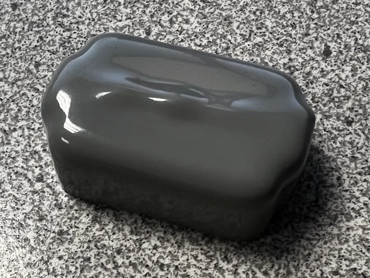
Its just a little shorter, but the spring makes up the difference and this leaves room in case the DI box’s internal pads are fixed.


Finally, I cut out a small notch in the panel of the battery carrier to allow the wires to pass through.

…while I was waiting for the 9V pad adapter to arrive, I remembered I have an old BOSS TU-12H tuner somewhere. I couldn’t find it at the moment, but I could remember its feel in my hand pretty well, so I cut a piece of acrylic to a size I thought would be close. It didn’t need to be perfect, just needed to be a large enough surface to use adhesive on the back of the tuner and hold it.
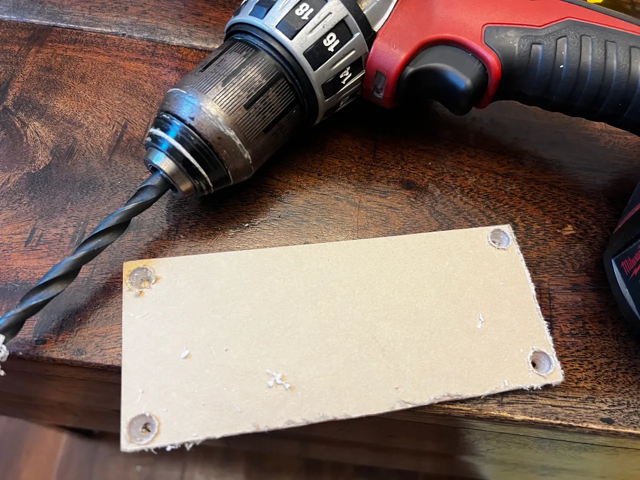
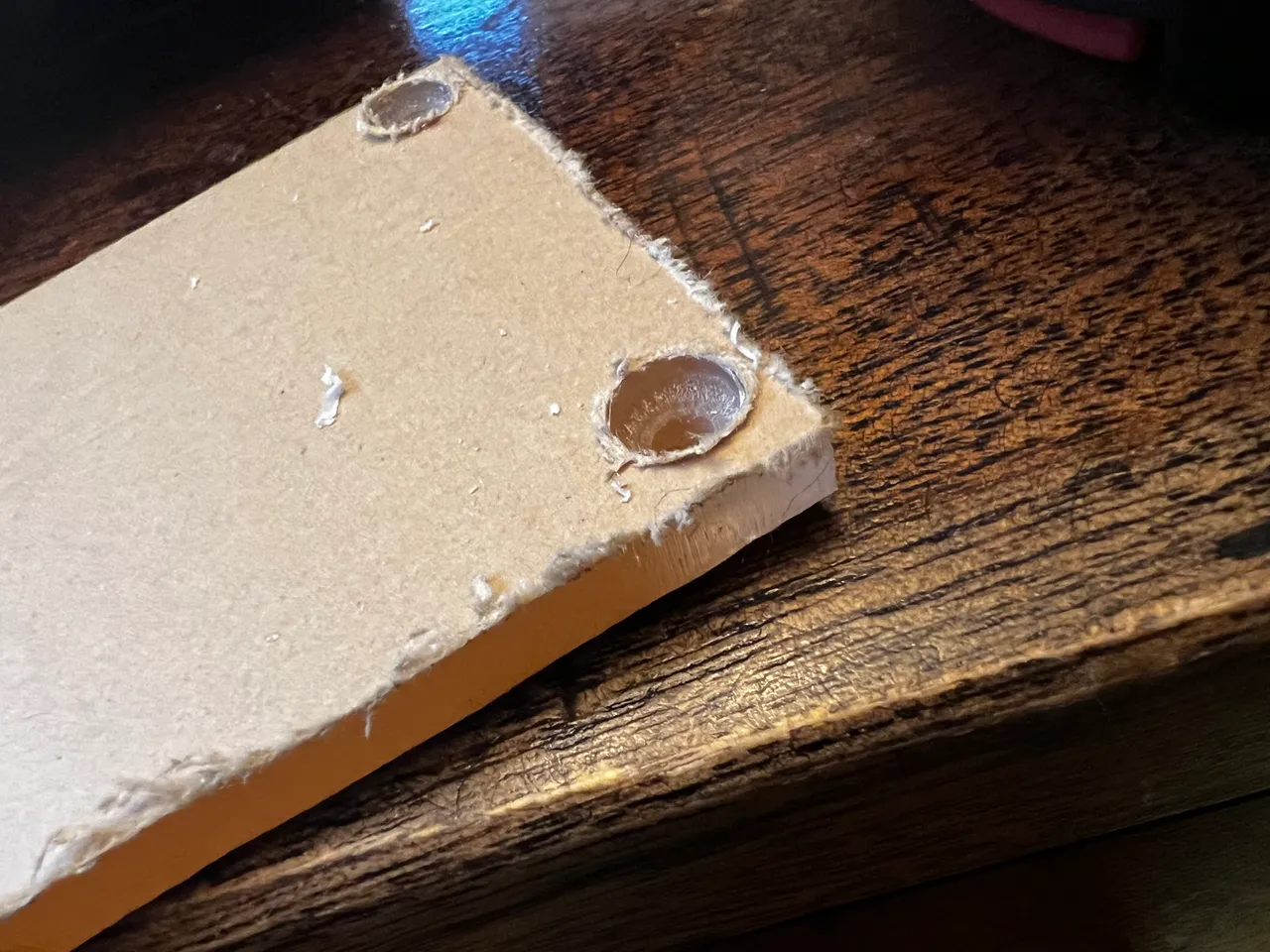
I guessed a size from memory and cut it out. Next I put holes with capscrew countersink holes in the corners. I just drilled gentle and slow with a larger bit until roughly half way through the material, then switched to the smaller bit. This should allow the screws to be recessed once fastened so they don’t impede the adhesive’s ability to secure the tuner.

Once my panel was prepped (I was surprised to find that the piece I had cut was a perfect fit for the space! I hadn’t even really thought about it 🤣), I eyeballed a good spot and threw in a standoff tall enough to clear the 9V supply.
I fastened the panel down securely, set it in position, and drilled the second standoff hole right through the panel and (mostly) straight down.
I fastened the panel to both standoffs and used the open holes as guides to drill for their standoffs. Once the holes were drilled, I removed the protective film from the acrylic panel and applied the adhesive, but before finalizing this part, I needed to put the new wires in the terminals to power the tuner.

I cut the cable off of a broken mouse, so the wires are just USB signal grade, 22AWG. To ensure I’m not adding impedance or heating up wires, I paired then together, Red with Black & Green with White going together.

Next I just installed the wires, putting red on the positive terminal…good thing I went with terminals instead of direct solder 😁

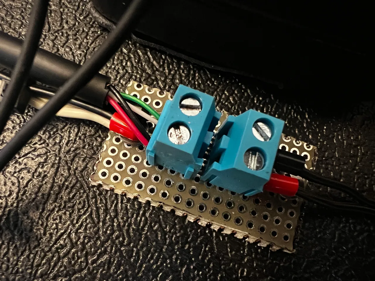
Just to be safe, before I covered it up I double checked and made sure my memory was correct, that this was a 1.3A brick. The RC-2 takes like 50mA and the TU-12H draws a much more noticeable 200mA, but together they’re still well under the limit, so the DI box should cause no issues.

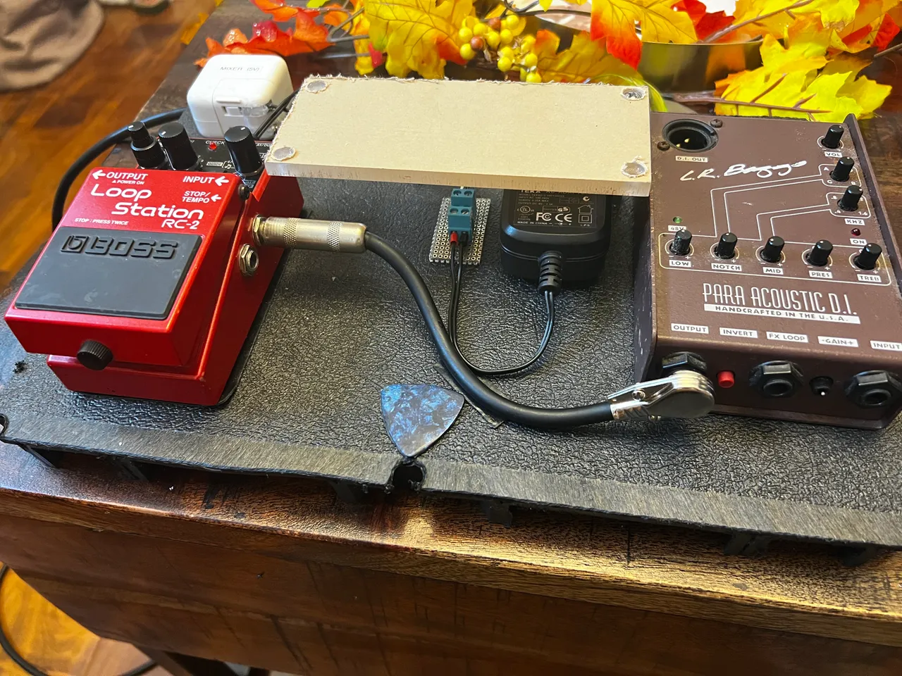
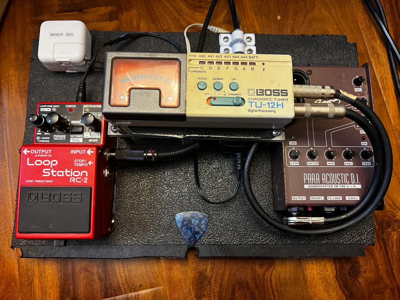
Here it is, all put together!

Next I had to go find my tuner. I haven’t needed a stage tuner in a long time…this was frustratingly difficult to find, but I did find it eventually.
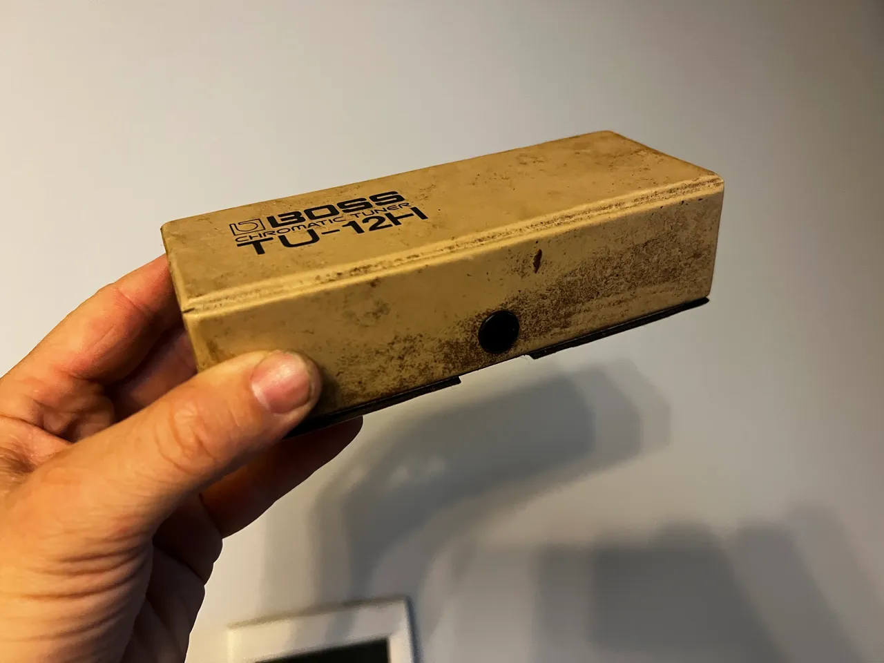
The case looks pretty nasty, I hoped the inside would be better.

It wasnt too bad!

So I stuck it on and routed the signal cables through it…and holy shit…it was perfect! I was pretty confident about the width, but I thought the length was going to be a little short when I looked at it after the cut - but no, it us just perfect.
The signal from my guitar will go through thr DI box first, so the tuner is hearing what I will be hearing, then from the tuner to the loop station, and from there to the mixer.
Next, I checked the unit for markings about the DC connection…

…and there it was…PSA. Well, at least this time I know what to do with that.

I always save old power supply bricks, so getting a new plug end was as easy as taking one out of the bag and cutting it off. I trimmed it to a decent length and stripped the ends.

I mocked it all up so I could cut the already connected cable to length.

After cutting and trimming the outer insulation back, I stripped the ends, twisted the red/black and green/white pairs together, then twisted the red wire to the negative/sleeve of the connector, and the white side to the positive/tip side of the connector (because PSA is wired backwards).
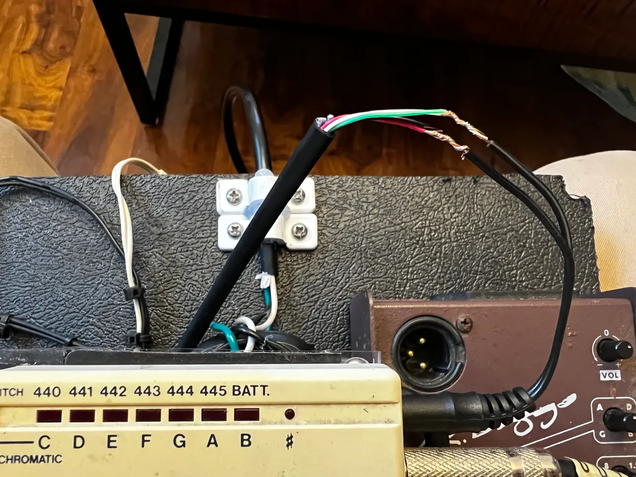
Then I soldered the wires so they’ll be secure and durable as I take this thing around playing.

Next I wrapped them. First individually, then all together, and afterwards I tested it out, and it works :)


After some waiting, the additional part came in, so I got to work.
Unfortunately, I made the mistake of planning for this connector to be female, and it’s not, so I had to throw in a female jack to connect to.
Before locking everything down, I took one last picture to remember which side is + and which is -. Because I’m using the pad to transmit power to a device, as opposed to receiving power from a battery, the jack will also need to be wired PSA…so I could have just flipped all the wires instead of cutting and swapping each wire individually - but no big deal, I was going to have to cut the mal connector off anyway.

I laid down a little bit of glue and stuck the wires in it to act as a strain relief.

Once the glue was dry I reinstalled the modified battery carrier.

Next, I cut the wires to the intended connector…I’m not a fan of running things this tight so later I would like to replace these wores, but for now I’m just anxious to put it all together, so I’m gonna use what I got.

Things were uncomfortably tight, but I soldered the wires to the new jack.

I tested it out and everything powered uo nicely.

On first testing plus trying to learn the loop station, I did get the station to kind of loop, but my timing was bad and the sound quality of the loop was really crappy compared to the live guitar. I am going to try rerouting the signal cables so it goes [ Tuner, Looper, DI, Mixer ]…but for now, I’m honestly just excited to share this story!
AC/DC Inverter
I have something like this in mind for practicing. Next summer, when I start practicing out at the lake again I’ll be able to connect my whole sound system (I might have to substitute a small practice amp for the powered speaker), so hopefully I’ll be learning how to use the loop station as things unfold…that wiuld add an entirely new dynamic to my performances, but so far I’ve never managed to tackle the challenge of learning how to use the loop station.
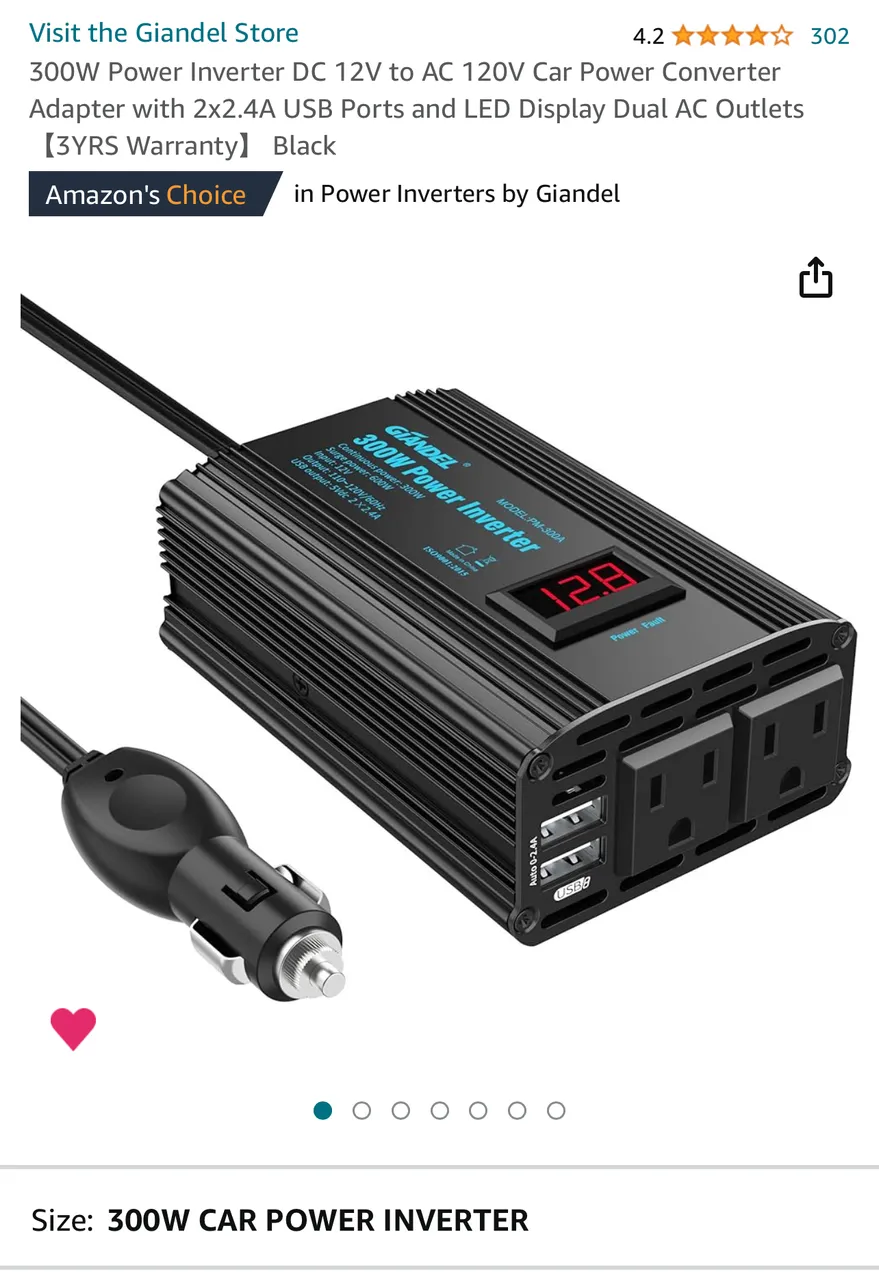
I don’t have this yet, but hope to get it in time to start practicing with the pedal board in the summer of 2024.
So, thats my setup currently! All these things will come together not just to help me play noisy bars, but also with any luck, the loop station will enable me to add a new dynamic to my performances.
UPDATES:
1: First run with the pedal board
2: I have a suspect for the hum. I noticed a faint tick in the background that matched the metronome light on the loop station, so it was certainly introducing at least some noise…although whether or not it’s coming from the power supply is yet unknown. However, I found this response to a question about noise in pedals in general:

Thanks for checking out some more of my work! As always, I hope you enjoyed witnessing as much as I enjoyed creating!
© Photos and words by @albuslucimus, except where otherwise indicated.

If you enjoy my content, check out the Albus Index!
Here you’ll find links to various post-groupings, so you can find all posts related to a specific topic quickly. Topics include lists of brewing recipes, flutes, crypto talks, rucking posts and an index of all acoustic covers. The lists are updated as new content is added, so they can always be used to quickly navigate my content.
@albuslucimus has officially hard-forked. @rorykl is now the home for pretty much all acoustic singer/songwriter work.
I created a second account (@rorykl) in May 2023 to be my professional side. It’s a totally separate thing, strictly acoustic playing and singing. Because I don’t want to post duplicate material from two accounts, this account is now the home for all my acoustic singer/songwriter type stuff.
I’ll be using this as my account to share with bars and venues etc., so it will be a home for acoustic covers, live performances and auditions…pretty much, if I’m playing a stringed instrument amd singing, this is where I’ll be doing it…unless I’m doing it while operating a motor vehicle ;)
Click or tap the profile banner below to check it out!