ESPAÑOL
Hola amigos, en ocasiones se nos presentan problemas con nuestros equipos electrodomésticos en casa y los llevamos a un técnico y muchas veces terminamos pagando una elevada suma de dinero por una falla sencilla que en ocasiones solo teniendo un mínimo de conocimiento podemos resolverlo nosotros mismos ahorrándonos el dinero y a la vez adquirir experiencia en este tipo de reparaciones.
En este momento les estaré comentando sobre una falla que suele suceder en los Televisores de Tubos de Rayos Catódicos (TRC). Esta falla consiste en que se dañan los colores del TV, tornándose la imagen en pantalla de un color específico, ya sea Roja, Verde o Azul, según el color que presente problema. Esto se debe a que las imágenes que se observan en la TV son combinaciones de los colores principales Rojo, Verde y Azul (RGB), y si falla alguno de estos, pues la imagen se torna roja, verde o azul, según sea el caso.
Esta falla suele estar provocada por varios factores, pero generalmente la causa está dada por una avería en uno de los tres transistores que manejan los colores del TV.
Mi experiencia con el TV del que te voy a hablar es que al mismo se le tornó la pantalla en un color verdoso y las personas y objetos se veían verdes, producto a la ausencia del color rojo.
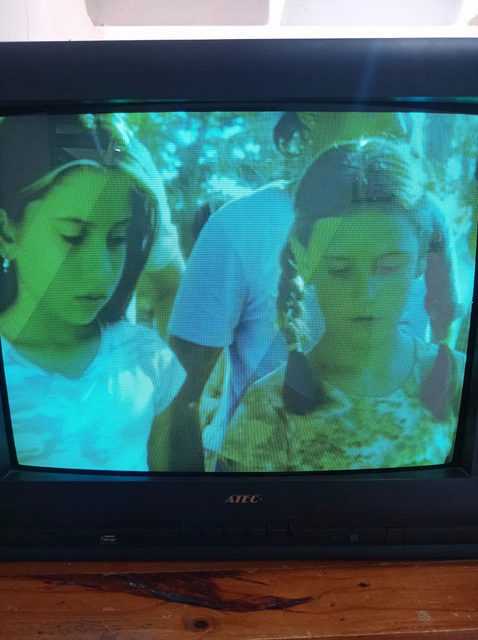
Imagen verde por la ausencia del color rojo debido a un mal funcionamiento en el circuito que maneja dicho color.
En este TV la imagen se torna verde, pero pudiera ser roja o azul, en cualquier caso la solución consiste en revisar los transistores RGB como suelen llamarles o amplificadores de colores RGB, y soldar nuevamente sus conexiones o sustituirlos en caso de estar deteriorados.
Estos transistores se pueden localizar fácilmente, pues se encuentran en la Tarjeta base del cinescopio y en ella se amplifican las señales de los colores, en lo adelante haré referencia a esta tarjeta como Tarjeta C, la cual está como mencioné, en la parte trasera del tubo de pantalla, adherida al yugo del mismo como te mostraré más adelante.
Paso a paso durante la reparación.
- Primeramente, se retiran los tornillos de la parte trasera del TV, como se señala en los círculos de la siguiente imagen.
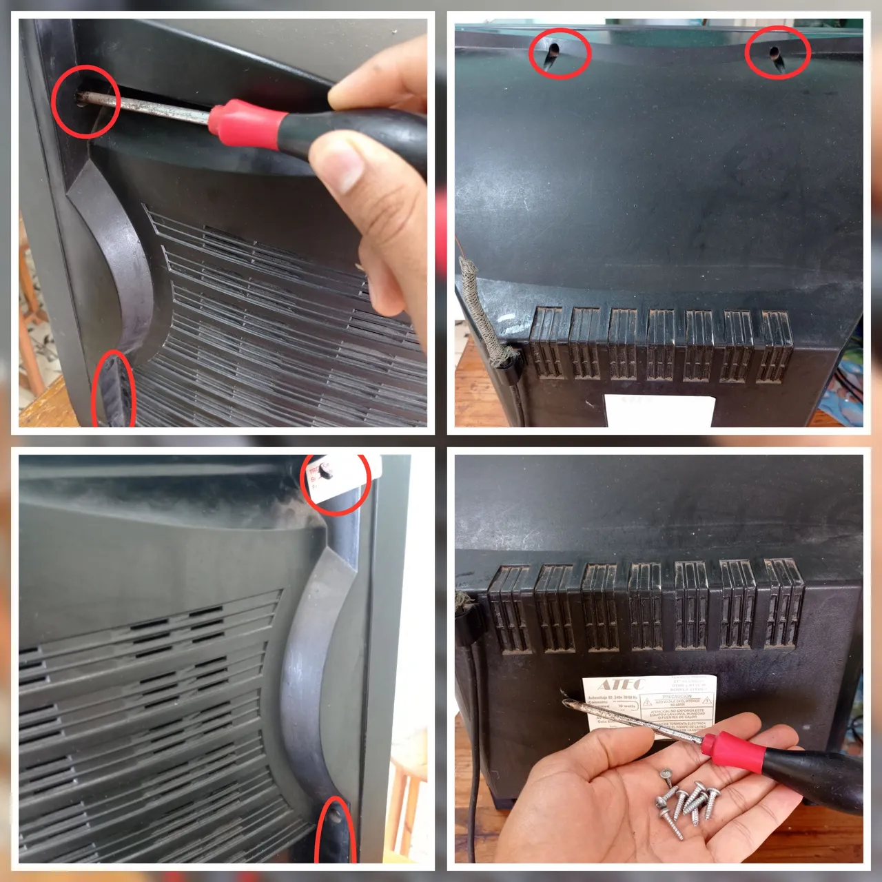
Extraer los tornillos de la carcasa trasera.
Extraer la carcasa y acceder al interior del TV.
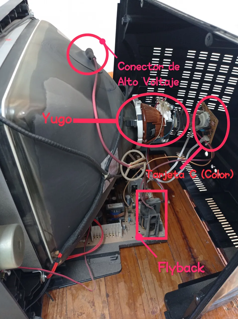
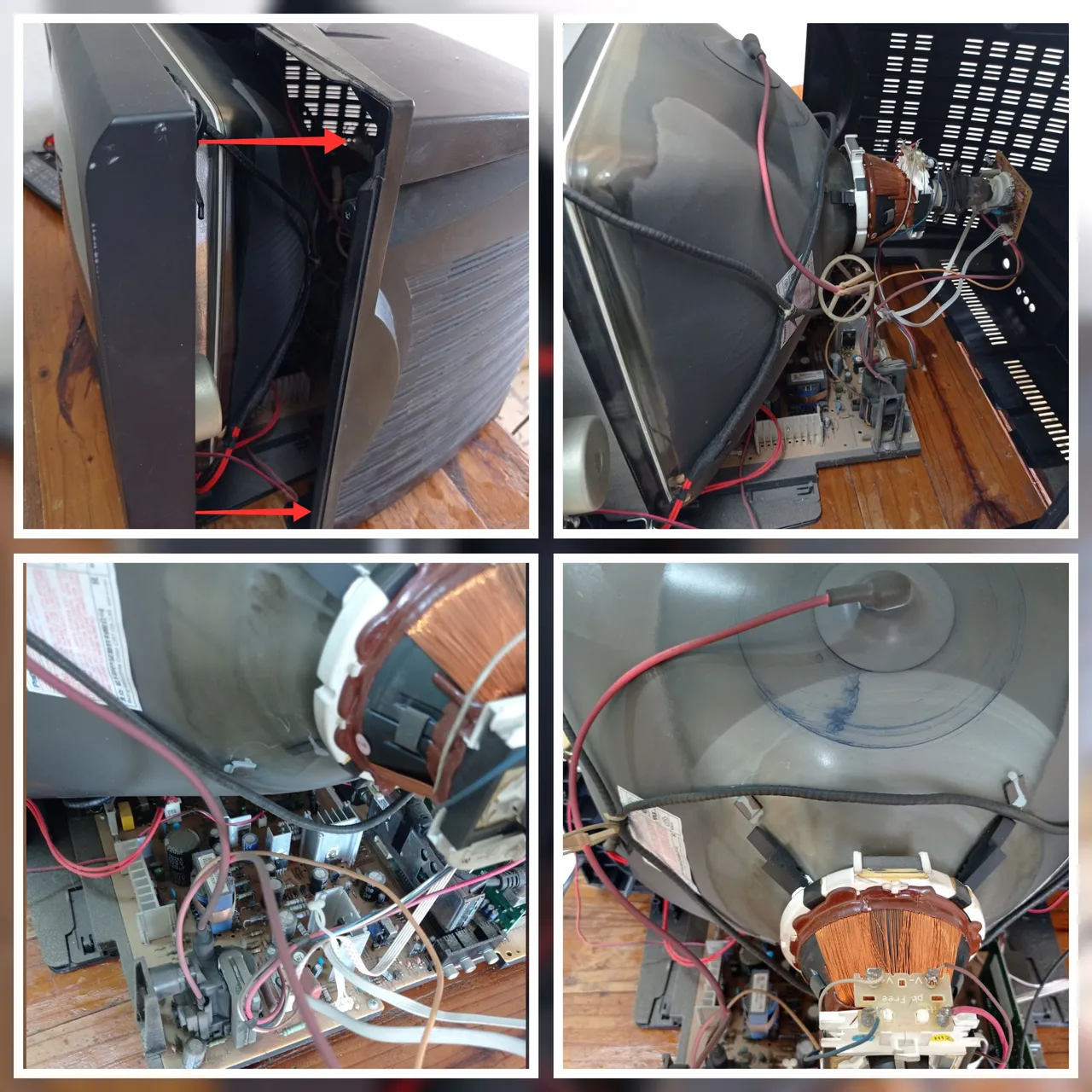
Algunas de las partes principales del TV a las que haré alusión más adelante.
De abajo hacia arriba: Flyback, Yugo(izquierda), Tarjeta C(Color) (derecha), Conector de alto voltaje.
En la imagen anterior se muestran algunas partes del TV, la falla a la que hago referencia se deberá trabajar en la ¨ Tarjeta C ¨ señalada anteriormente, ya que ahí se alojan los transistores que amplifican las señales correspondientes a los colores Rojo, Verde y Azul; sin embargo, señalo también el Flyback y el conector del alto voltaje para que sean identificados y bajo ningún concepto sean manipulados, ya que no es necesario trabajar en esta zona para reparar esta avería. Y principalmente por el hecho de que estos componentes manejan altos voltajes y aun después de apagar el TV y desconectarlo de la toma eléctrica, queda almacenado en el tubo de pantalla este alto voltaje, por lo que existe un riesgo de choque eléctrico si se entra en contacto con el interior del conector de alto voltaje. Para trabajar en esta zona previamente se debe descargar a tierra todo ese potencial almacenado en el tubo de pantalla, aplicando un procedimiento que no describiré en el post, ya que no será necesario trabajar en la zona antes mencionada, solo hay que tener en cuenta que no debemos quitar el conector del alto voltaje.
- Luego extraemos la Tarjeta C, identificamos los transistores que controlan la intensidad de los colores y mediante una inspección visual, verificamos el estado de las soldaduras de sus pines, así como las soldaduras del resto de componentes en dicha tarjeta.
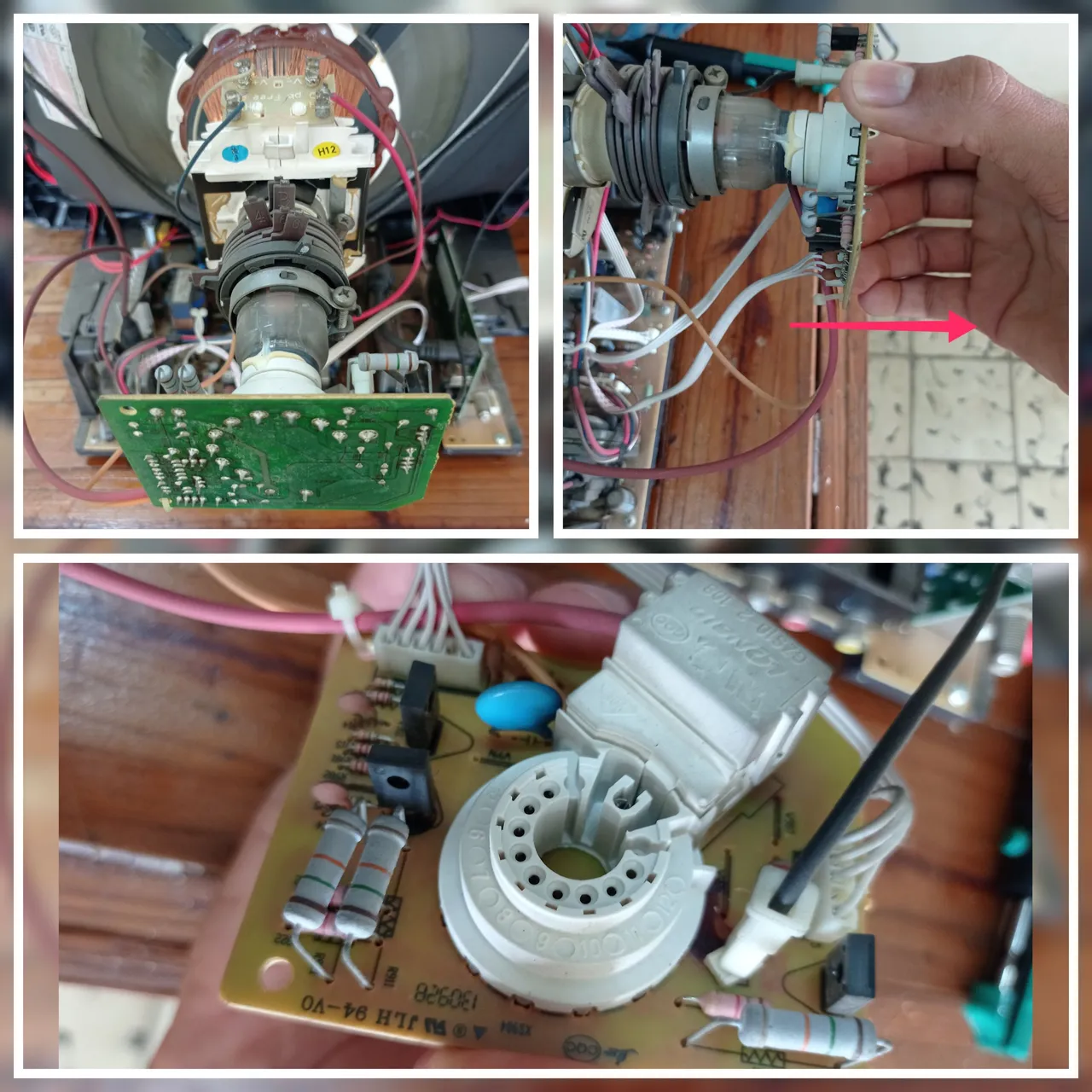
Extracción de la Tarjeta C (color)
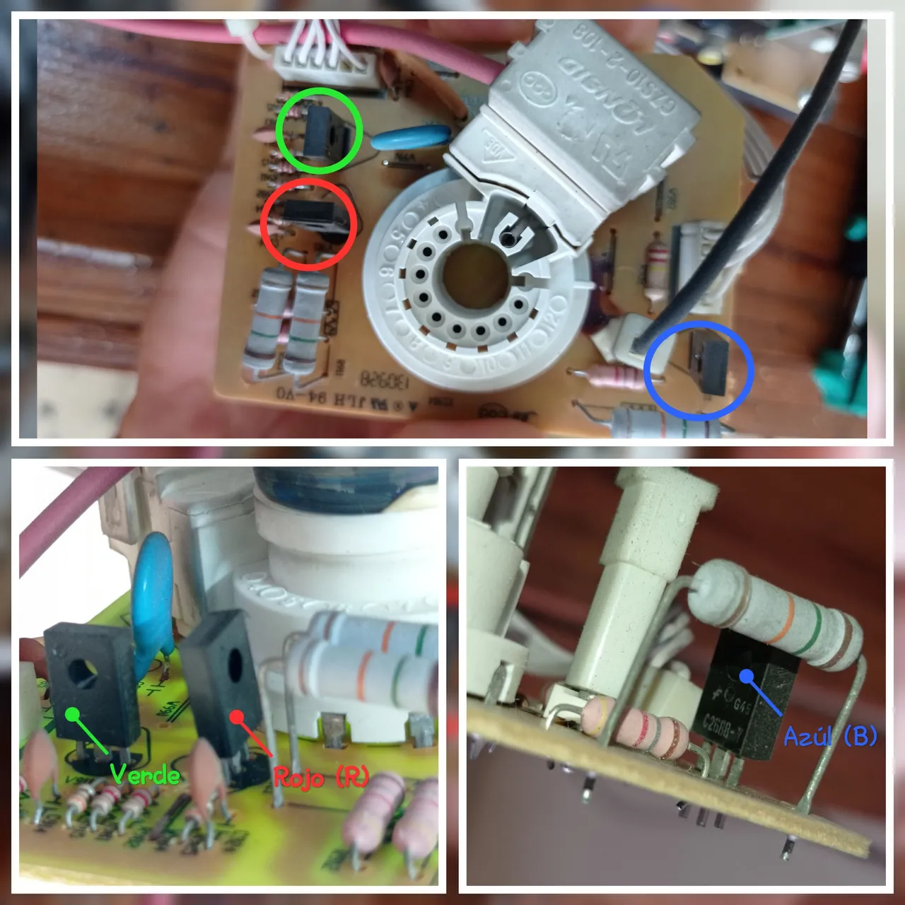
Transistores que manejan los colores RGB, cada uno señalado con el color correspondiente que amplifican.
Al realizar la inspección ocular pude percatarme que existían soldaduras frías o quebradas en los pines del transistor que maneja el color Rojo (R), lo que provocaba una deficiencia de este color en la imagen, dando como resultado una tonalidad verdosa en las imágenes del TV.
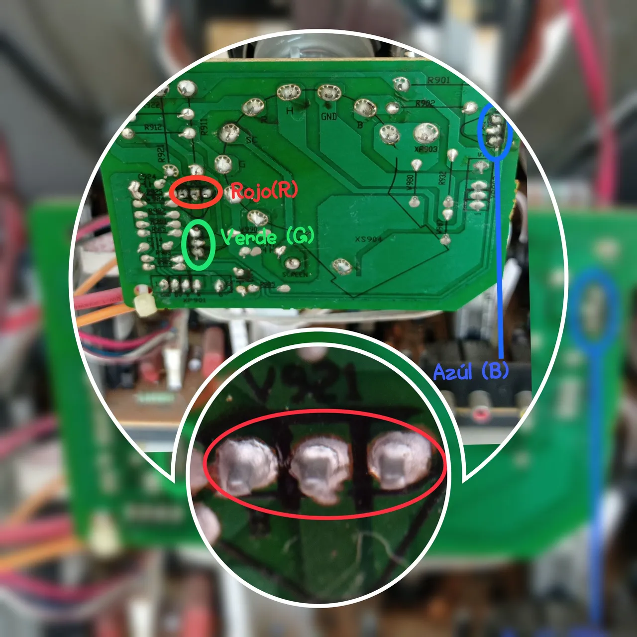
Vista inferir de la Tarjeta C, donde se identifican los pines de los transistores RGB. Se aprecia señalado en un óvalo rojo, que las soldaduras de los pines del transistor que amplifica la señal del color Rojo están quebradas.
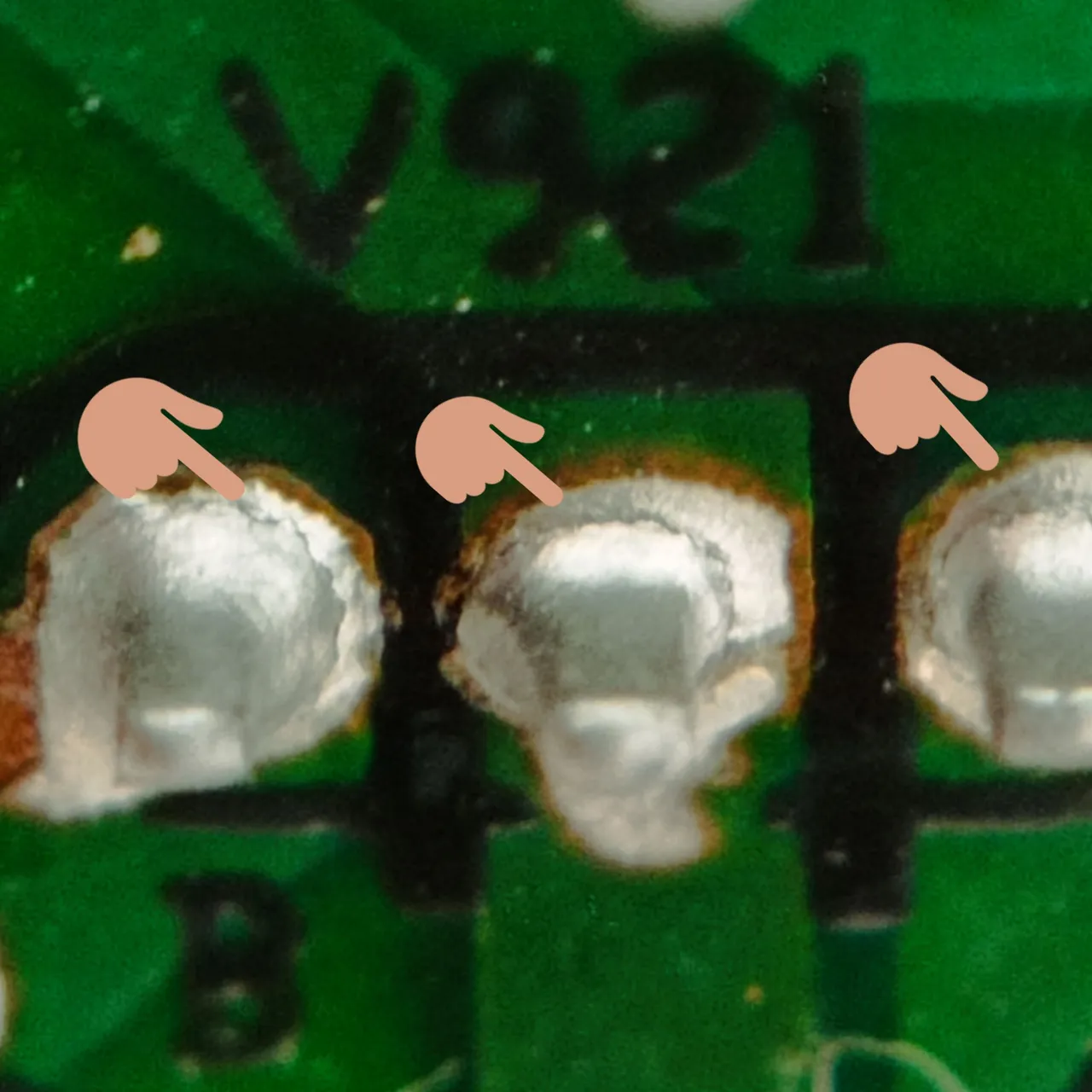
Soldadura de los pines del transistor del color Rojo, totalmente quebradas.
- Una vez identificado este problema, con ayuda de un cautín y estaño, se procede a mejorar las soldaduras de dichos pines y por precaución el resto de las soldaduras de los componentes de la Tarjeta C.
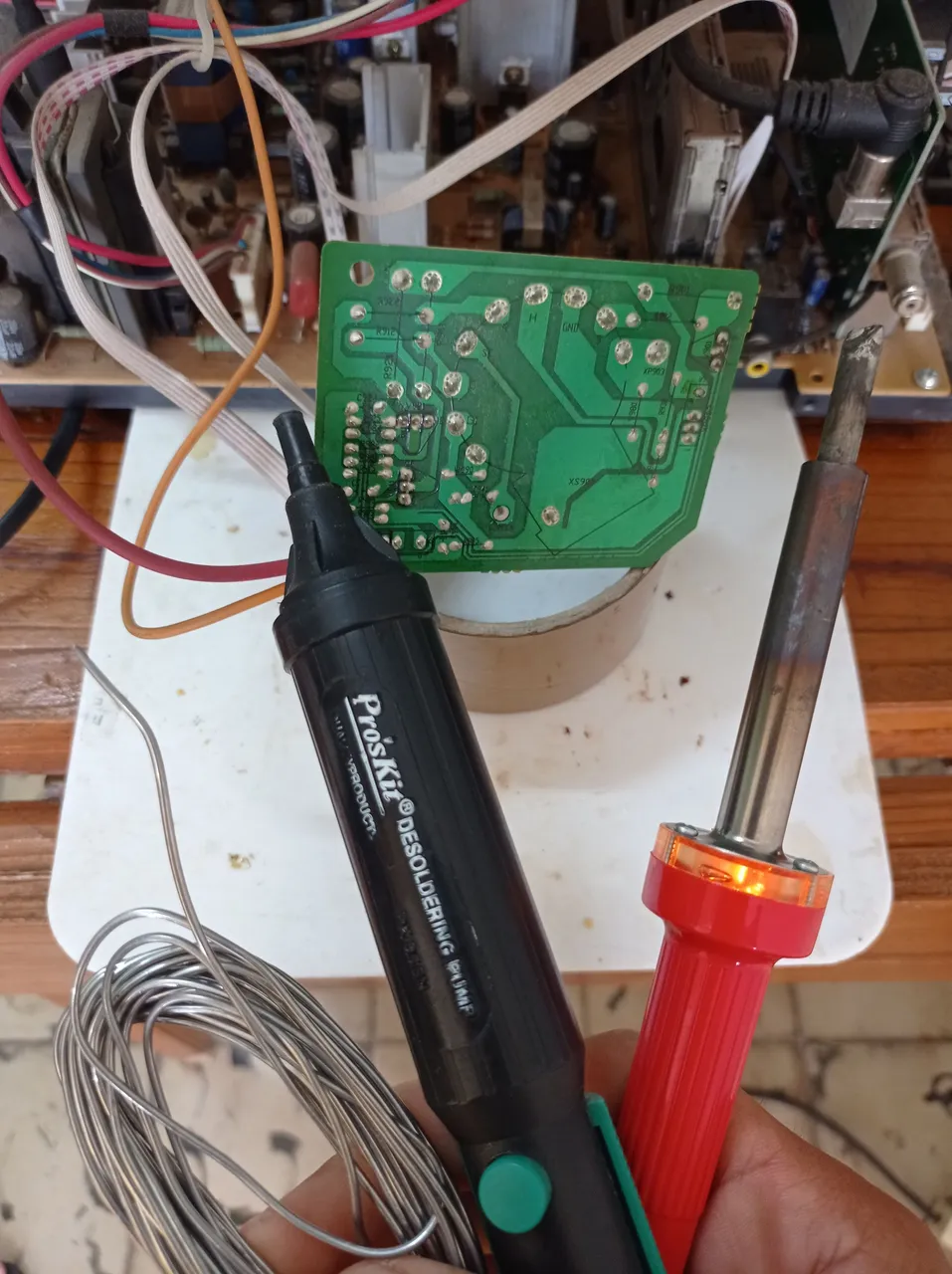
Estaño, bomba chupa estaño (yo la utilicé para extraer el estaño viejo, pero en caso de no tenerla se puede prescindir de ella) y soldador cautín.
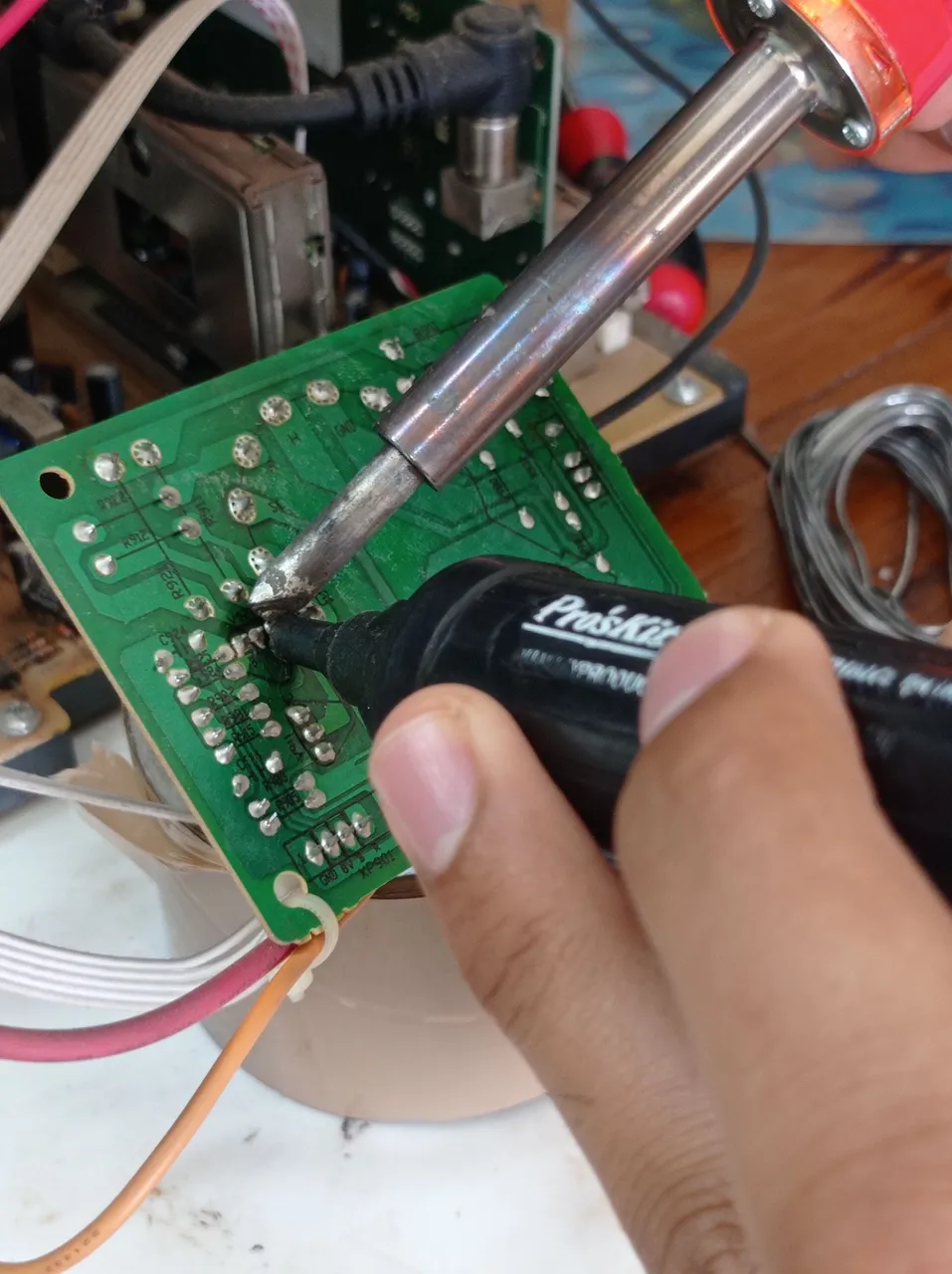
Extracción del estaño viejo para luego volver a soldar.
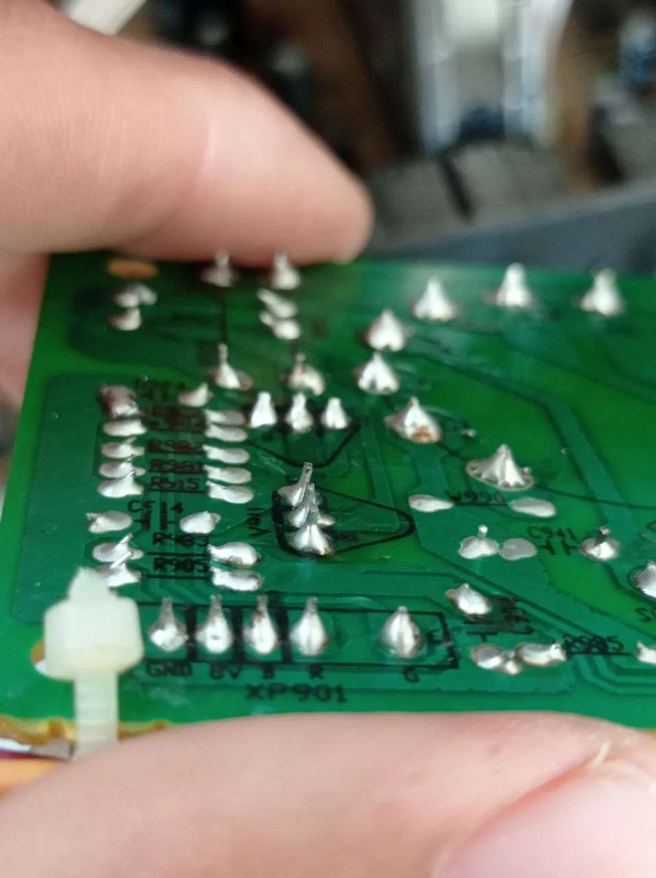
Tarjeta C con todas las soldaduras mejoradas.
- Después de soldar nuevamente los transistores y demás componentes, se coloca la tarjeta en su lugar y se comprueba que todo esté correctamente conectado, luego de esto se enciende el TV para verificar si se solucionó la falla.
- Efectivamente, después del proceso descrito con anterioridad, quedó resulta la falla, como bien se puede comprobar en las imágenes anteriores, mejorando considerablemente la calidad del video.
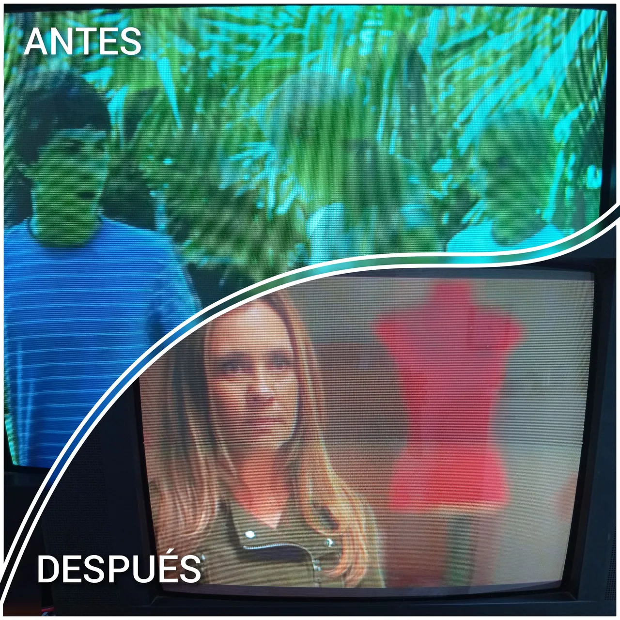
Un antes y un después.
- Ya por último se desconecta el TV de la toma eléctrica y se coloca la tapa trasera aplicando el proceso inverso a como se empezó a desarmar.
! Listo¡, a seguir disfrutando de la programación televisiva jjj.
Amigos ya ven que algunas fallas pueden solucionarse relativamente fácil, si tienes un mínimo conocimiento de electrónica o tienes habilidades de soldadura con el cautín, tomando las precauciones necesarias como te comenté anteriormente para evitar accidentes, podrás solucionar este problema siguiendo el proceso descrito. Espero que mi experiencia haya sido de interés para alguien, de ser así, agradezco que me lo dejen dicho en los comentarios.
Saludos y hasta la próxima. 😉
Las imágenes son de mi autoría y fueron tomadas con un celular Xiaomi Redmi Note 9.
Imágenes editadas en la aplicación "Galería" del teléfono y "Foto Collage-GridArt"
Portada creada en Canva
Puedes verme en Facebook
ENGLISH
Hello friends, sometimes we have problems with our appliances at home and we take them to a technician and often end up paying a large sum of money for a simple failure that sometimes just having a minimum of knowledge we can solve it ourselves saving money and at the same time gain experience in this type of repairs.
At this moment I will be commenting on a failure that usually happens in the Cathode Ray Tube (CRT) TVs. This failure consists in that the colors of the TV are damaged, turning the image in screen of a specific color, either Red, Green or Blue, according to the color that presents problem. This is due to the fact that the images that are observed in the TV are combinations of the main colors Red, Green and Blue (RGB), and if any of these fails, the image becomes red, green or blue, depending on the case.
This failure is usually caused by several factors, but generally the cause is given by a failure in one of the three transistors that manage the colors of the TV.
My experience with the TV I am going to tell you about is that the screen turned greenish and people and objects looked green, due to the absence of the red color.
Green image due to the absence of the red color due to a malfunction in the circuit that handles this color.
In this TV the image turns green, but it could be red or blue, in any case the solution is to check the RGB transistors as they are usually called or RGB color amplifiers, and re-solder their connections or replace them if they are damaged.
These transistors can be easily located, because they are in the kinescope base card and in it the color signals are amplified, hereinafter I will refer to this card as Card C, which is as I mentioned, in the back of the screen tube, attached to the yoke of the same as I will show you later.
Step by step during repair.
- First, remove the screws from the back of the TV, as indicated by the circles in the following image.
Remove the screws from the rear casing.
Removing the housing and accessing the inside of the TV.
Some of the main parts of the TV that I will refer to later.
From bottom to top: Flyback, Yoke (left), C(Color) Card (right), High Voltage Connector.
In the previous image some parts of the TV are shown, the failure to which I make reference will have to work in the ¨ Card C ¨ indicated previously, since there the transistors that amplify the signals corresponding to the colors Red, Green and Blue are lodged; nevertheless, I also indicate the Flyback and the connector of the high voltage so that they are identified and under no concept they are manipulated, since it is not necessary to work in this zone to repair this failure. And mainly due to the fact that these components handle high voltages and even after turning off the TV and disconnecting it from the electrical outlet, this high voltage is stored in the display tube, so there is a risk of electric shock if it comes into contact with the inside of the high voltage connector. To work in this area previously must be discharged to ground all that potential stored in the screen tube, applying a procedure that I will not describe in the post, since it will not be necessary to work in the area mentioned above, just keep in mind that we must not remove the high voltage connector.
- Then we remove Card C, identify the transistors that control the intensity of the colors and by visual inspection, we verify the state of the soldering of its pins, as well as the soldering of the rest of the components on the card.
Removal of Card C (color)
Transistors that drive the RGB colors, each marked with the corresponding color they amplify.
Upon visual inspection, I noticed that there were cold or broken solder joints on the pins of the transistor that handles the color Red (R), which caused a deficiency of this color in the image, resulting in a greenish tone in the TV images.
Inferior view of Card C, where the pins of the RGB transistors are identified. It can be seen marked in a red oval, that the solder joints of the pins of the transistor that amplifies the red signal are broken.
Soldering of the pins of the red transistor, totally broken.
- Once this problem is identified, with the help of a soldering iron and solder, we proceed to improve the soldering of these pins and, as a precaution, the rest of the soldering of the components of the C Card.
Solder, solder pump (I used it to extract the old solder, but if you don't have it, you can do without it) and soldering iron.
Removal of old tin for re-soldering.
C-card with all solder joints improved.
- After re-soldering the transistors and other components, the board is placed in its place and everything is checked to make sure it is correctly connected, then the TV is turned on to verify if the fault is solved.
- Indeed, after the process described above, the fault was solved, as can be seen in the images above, improving the video quality considerably.
A before and after.
- Finally, the TV is disconnected from the electrical outlet and the back cover is placed applying the reverse process to how it was disassembled.
! Ready, to continue enjoying the television programming jjj.
Friends, you can see that some failures can be solved relatively easy, if you have a minimum knowledge of electronics or have soldering skills with the soldering iron, taking the necessary precautions as I mentioned above to avoid accidents, you can solve this problem by following the process described. I hope my experience has been of interest to someone, if so, please let me know in the comments.
Greetings and see you next time. 😉
The images are of my authorship and were taken with a Xiaomi Redmi Note 9 cell phone.
Images edited in the "Gallery" application of the phone and "Photo Collage-GridArt"
Text translated to English in Deepl translator.
Cover created in Canva
You can see me at Facebook