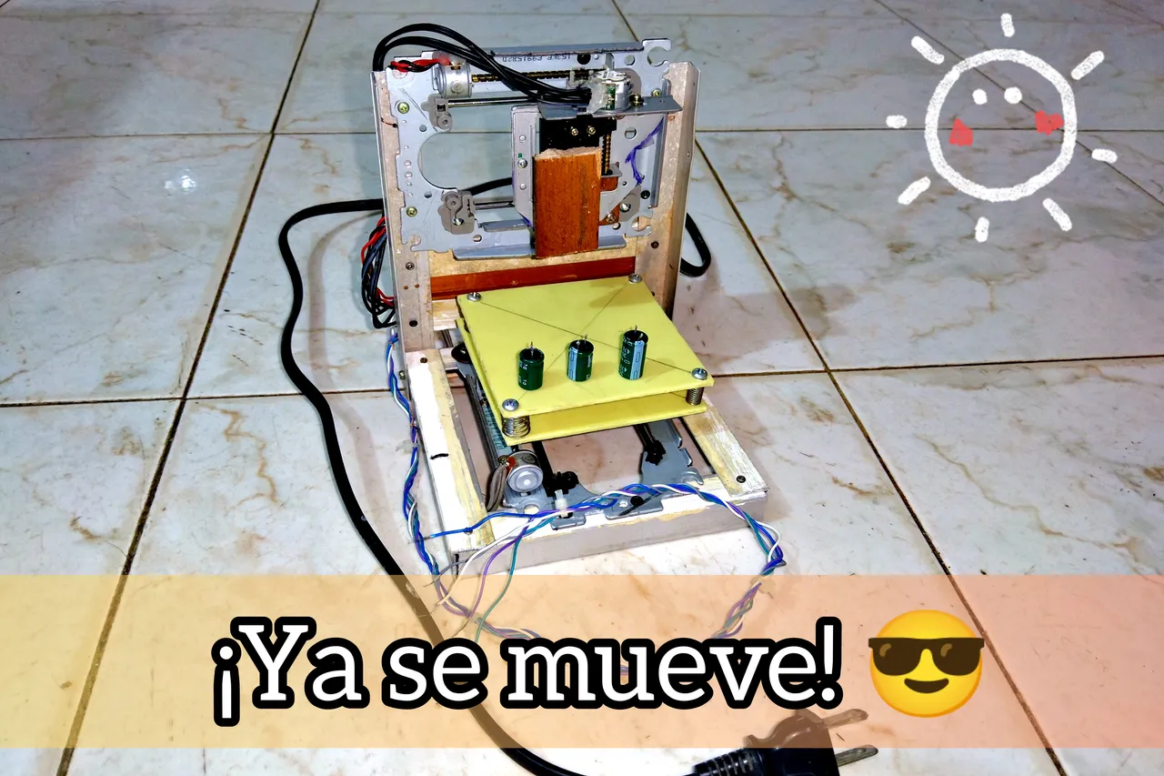
Hello, today I come to show you the new updates of the 3D printer that I am building, I have been very busy lately and I feel that I have not made much progress, although my mom tells me "don't look how much you lack, but how much you have" and I really have a lot .
I already got movement in all axes and built a more solid and resistant base based on aluminum.
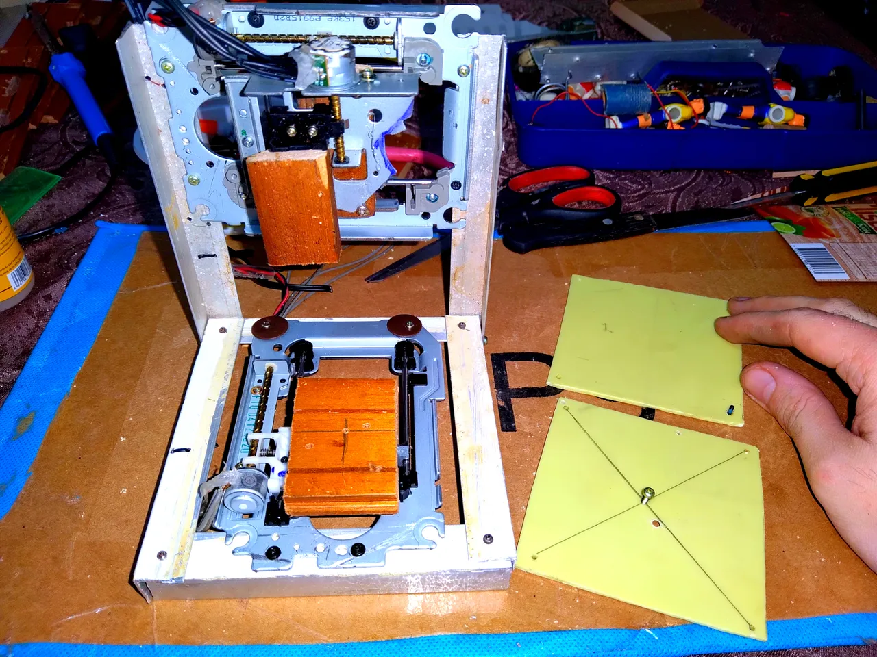

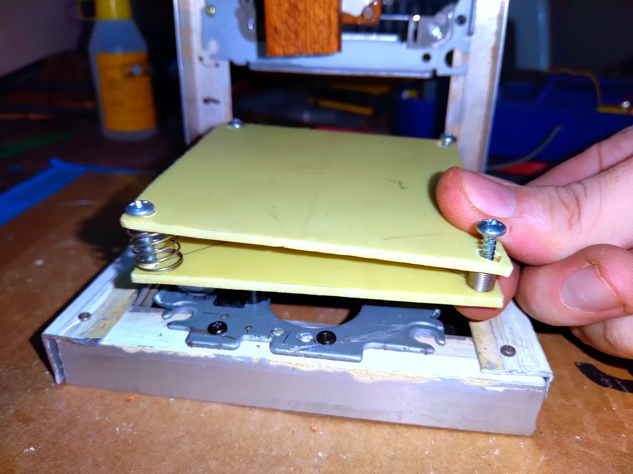
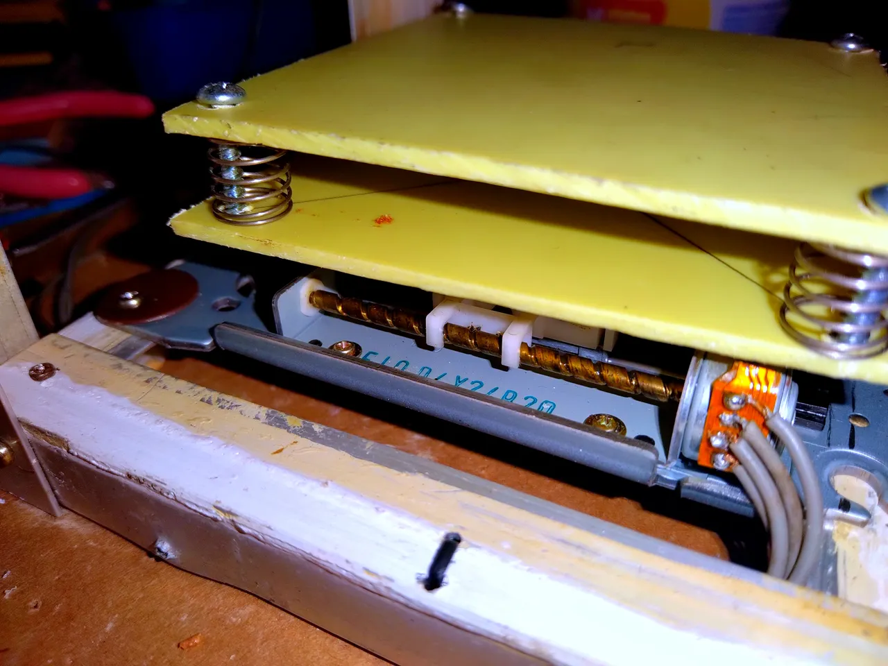
Another thing I did was make the leveling table, this is much easier than it seems, you just have to make two identical pieces and drill holes in both of them in the 4 corners to later join them with screws and springs in the middle.
The idea is that by slowly adjusting each screw we can get a perfectly level surface and so that what we print is properly printed and not with some kind of inclination. My base is 9x9 cm, which may not seem like much and it is not, although it will come in handy for making key rings and miniature figures.
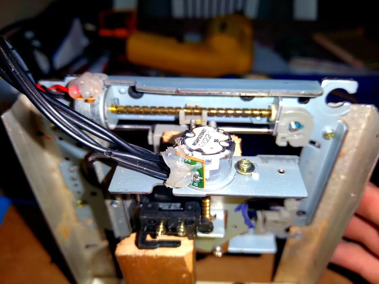
Another thing I did is take measurements to know how to design the plastic ejector, for this I simply placed the horizontal axis and the depth axis in the center of their rails and started to take measurements, I'll show you how I did it.
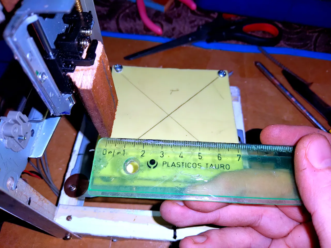

By making simple measurements with a ruler, I can tell that the tip of the ejector needs to be 1.2 cm offset to the right and 3.4 cm forward to achieve perfect centering on the level surface.
Having these measurements I can start designing it on the computer using 3D design programs, I personally like SketchUp a lot and it is the one that I will possibly use to design this piece to build it later. In fact, I was originally planning to have it ready for this post, but the structure change changed the measurements and now I have to design everything from scratch 😂
Something was bothering me and what I decided to dedicate some time to was ordering the cables. Testing the tangled cables was extremely exhausting, not to mention that they were located at the rear of the structure and that made it difficult to visualize the test results.
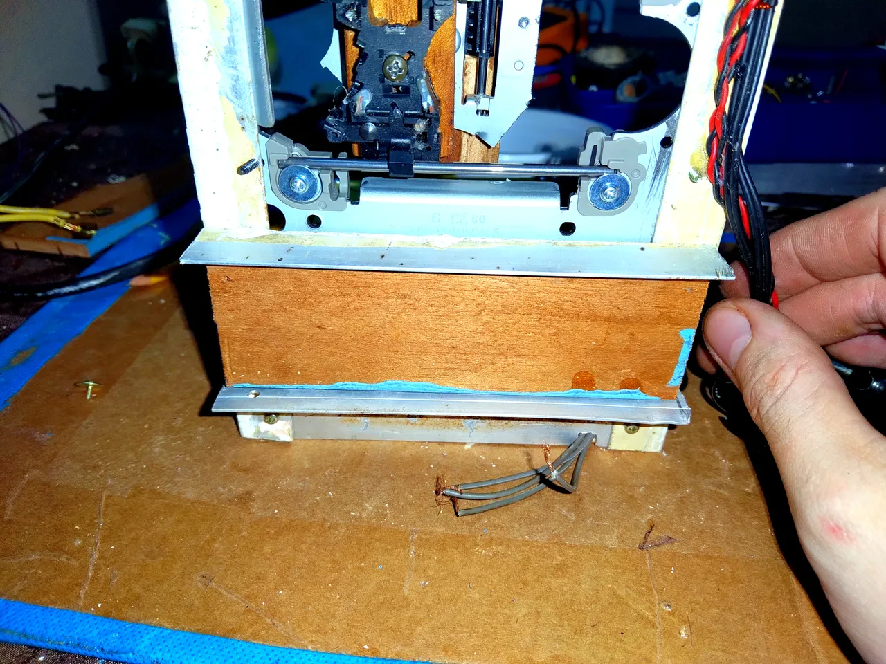
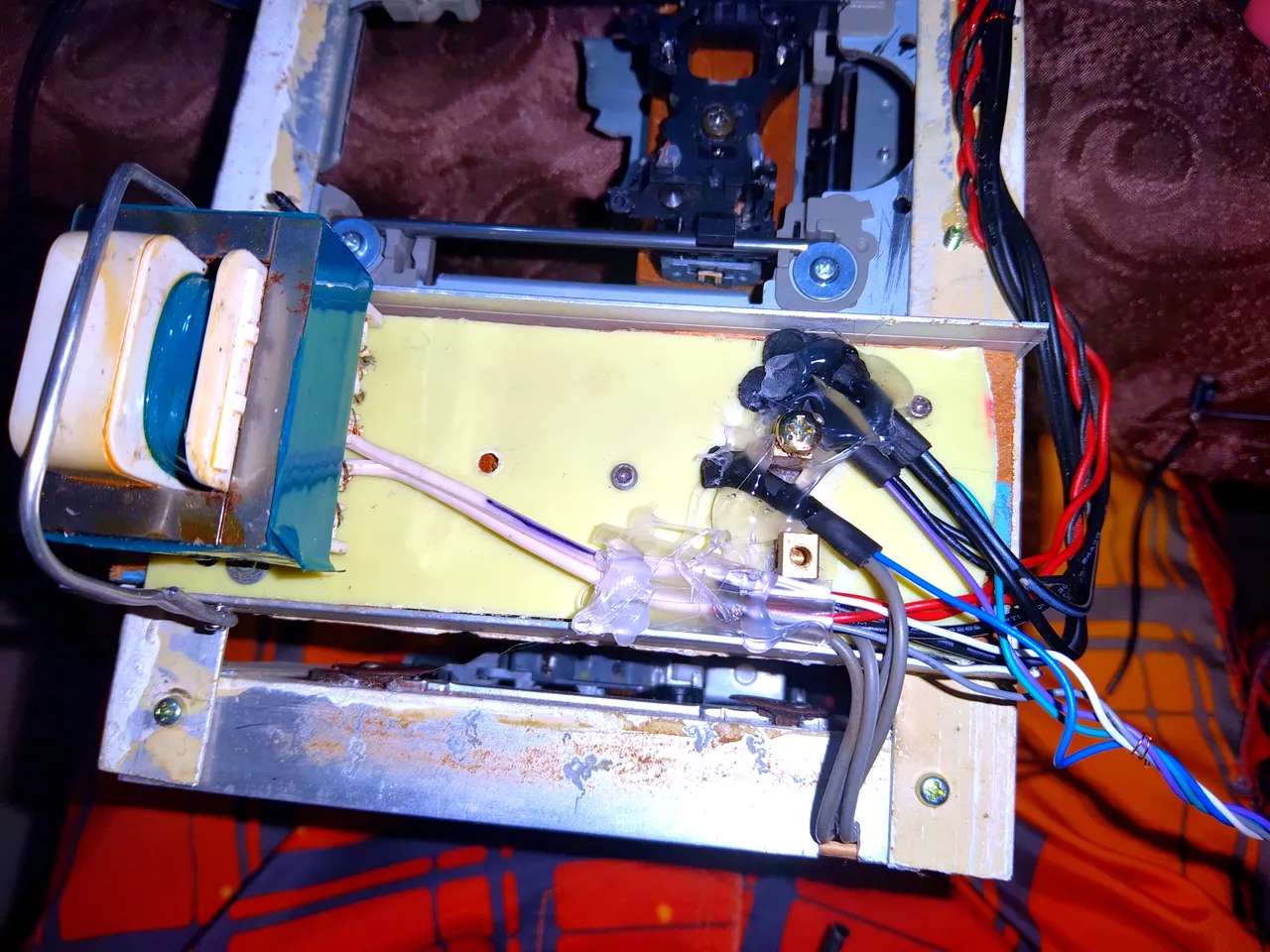
In order not to be struggling, I put everything in order. I made a small junction box with a piece of wood and anchored the transformer and all the connections to it, obviously everything already soldered with tin. Although it wouldn't be the first time that I glue everything with hot silicone and then I have to take everything off due to a badly connected cable 😂
Also this time I made an effort to check that everything was together and that there was continuity in all the connections before sealing everything with hot silicone.

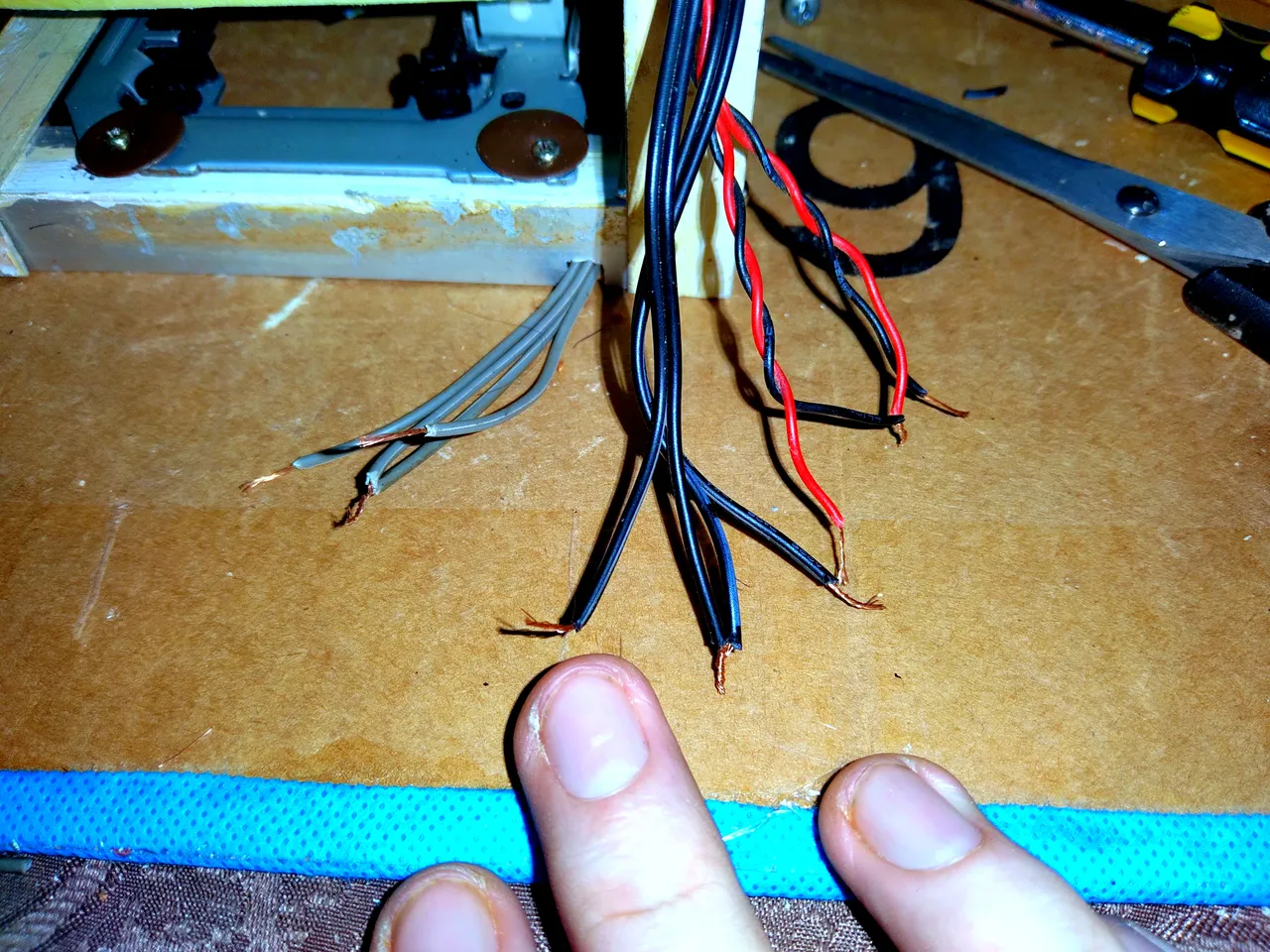
In the end I got something like this, just 5 cables that are going to make my life easier. Two of them correspond to food and the 3 most colorful each correspond to an axis. The connections are fairly simple, although without a controller it becomes extremely tedious to perfect.
Let me explain, to make them work I must connect one of the connectors of a capacitor to one of the cables of some axis, then by connecting the other output of the capacitor to one or the other power cable I can vary the direction of rotation of the motors, that is to say , make it go up or down, go from right to left and forward and backward.
Tests in the depth axis. (X)
Tests on the horizontal axis. (Y)
Tests on the vertical axis. (Z).
Although everything seems to be going perfectly, unfortunately it is not. The capacitors need to be large enough to absorb the electrical pulses emitted by the motors when they are run and I can't get the right capacitance right now. In the GIFs it is not noticeable, although lying seems very unethical to me.
Not having the correct capacitors produces a small vibration in the motors, it's nothing special, I just have to keep testing capacitors until I get the right one for each motor. The vertical axis is the one that gave me the least problems and I managed to calm its vibrations, I'm still testing capacitors on the other 2 remaining axes.